Hyundai i-30: AVN System / USB jack
Schematic diagrams
| Circuit Diagram |

Description and operation
| Description |
The multimedia jack on the console upper cover is for customers who like to
listen to external portable music players like the MP3 etc., through the vehicle's
sound system when it is linked to this jack. The customer has this added option.
In case of distorted sound coming from the AUX-linked external music players,
the audio unit may not be defective but the output level of the player does
not match the specification of the AUX.

Repair procedures
| Removal |
| 1. |
Disconnect the negative(-) battery terminal.
|
| 2. |
Remove the floor console front tray.
(Refer to Body - "Floor Console Assembly")
|
| 3. |
Remove the multimedia jack (A) after disengaging the retaining clips
(B).
|

| Installation |
| 1. |
Connect the multimedia jack connector.
|
| 2. |
Install the multimedia jack.
|
| 3. |
Install the floor console front tray.
|
|

 AVN Remote Controller
Components and components location
Components
1. Left Remote
Control Switch (Audio + Hands free)
2. Right Remote
Control Switch
(Cruise+Trip Computer+ Smart Cruise)
Schematic diagrams
Circuit Diagram
[Audio]
[Audio + Bluetooth]
[Audio + Bluetooth + Voice]
[Trip + Cruise]
Repair procedures
Inspection
1...
 Mic
Mic
Repair procedures
Inspection
1.
Disconnector the negative (-) battery terminal.
2.
Remove the overhead console lamp...
Other information:
Hyundai i30 (PD) 2018-2025 Service Manual: Audio Unit
Components and components location Components Audio Connector Pin Information NO Connector A Connector B 1 Rear left speaker (+) - 2 Front left speaker (+) - 3 Front right speaker (+) - 4 Rear right speaker (+) Steering wheel key 5 - - 6 Door open USB data (HI) 7 IGN 1 USB VCC 8 ILL (+) - 9 DETENT - 10 Rear left speaker (-) MIC signal (+) 11 Front left speaker (-) ACC 12 Front right speaker (-) Battery (+) 13 Rear right speaker (-) - 14 - - 15 - - 16 - Speed 17 ILL (-) Steering wheel key GND 18 Antenna Power USB data (LOW) 19 USB GND 20 - 21 - 22 MIC signal (-) 23 - 24 GND Display Audio Connector Pin Information No Connector A Connector B 1 Rear door speaker (Left +) - 2 Rear door speaker (Left -) Mic_Signal (+) 3 USB Ground - 4 USB Data_High - 5 USB Data_Low Antenna power 6 USB_VCC Illumination (+) 7 Camera video MM CAN (High) 8 - - 9 - - 10 AUX Audio R Battery (+) 11 AUX Detect Battery (+) 12 Steering wheel remote Ground 13 Front door speaker (Left +) Ground 14 Front door speaker (Left -) Mic_Ground 15 Front door speaker (Right -) Mic_Signal (-) 16 Front door speaker (Right +) - 17 - - 18 - Vehicle speed 19 - Illumination (-) 20 Camera power ground MM CAN (Low) 21 Camera video ground - 22 - ACC 23 - - 24 AUX Audio L - 25 AUX Audio ground - 26 Steering wheel remote grond Door open 27 Rear door speaker (Right -) - 28 Rear door speaker (Right +) - 29 - - 30 - - 31 - - 32 Camera power ground IGN 1 33 Camera shield ground - 34 - - 35 - - 36 Camera_Detect 37 - 38 - Repair procedures Removal • When removing with a flat-tip screwdriver or remover, wrap protective tape around the tools to prevent damage to components...
Hyundai i30 (PD) 2018-2025 Service Manual: Vacuum Pump
Components and components location Components [KAPPA PE 1.0, MHEV] 1. Vacuum pump assembly 2. Wiring bracket Components [NEW-U 1.6, MHEV] 1. Oil screen 2...
Categories
- Manuals Home
- 3rd Generation i30 Owners Manual
- 3rd Generation i30 Service Manual
- Engine compartment
- Cruise control
- Trip computer
- New on site
- Most important about car
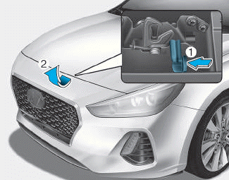
Bonnet
Opening the bonnet
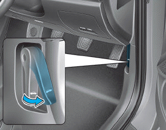
1. Park the vehicle and set the parking brake.
2. Pull the release lever to unlatch the bonnet. The bonnet should pop open slightly.

Copyright © 2025 www.hi30.net