Hyundai i-30: Body Electrical System / Power Door Mirrors
Hyundai i30 (PD) 2018-2025 Service Manual / Body Electrical System / Power Door Mirrors
 Power Door Lock Switch
Schematic diagrams
Circuit Diagram
Repair procedures
Removal
1.
Disconnect the negative (-) battery terminal...

Other information:
Hyundai i30 (PD) 2018-2025 Service Manual: Passenger Airbag (PAB) ON/OFF Switch
Description and operation Description • Driver can control the passenger airbag operating Condition (Enable or Disable) by using this PAB ON/OFF switch. • Passenger Airbag (PAB) ON/OFF Switch is installed in the crash pad side cover...
Hyundai i30 (PD) 2018-2025 Service Manual: Rear Wiper Motor
Repair procedures Inspection Rear Wiper Motor 1. Remove the connector from the rear wiper motor. 2. Connect positive (+) battery cables to terminal 4 and negative (-) battery cables to terminal 3 respectively...
Categories
- Manuals Home
- 3rd Generation i30 Owners Manual
- 3rd Generation i30 Service Manual
- Theft-alarm system
- Drive mode integrated control system
- To activate the ISG system
- New on site
- Most important about car
Turn signals and lane change signals
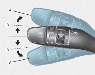
To signal a turn, push down on the lever for a left turn or up for a right turn in position (A). To signal a lane change, move the turn signal lever slightly and hold it in position (B).The lever will return to the OFF position when released or when the turn is completed.

Copyright © 2025 www.hi30.net