Hyundai i-30: Convenient features of your vehicle / Theft-alarm system
This system helps to protect your vehicle and valuables. The horn will sound and the hazard warning lights will blink continuously if any of the following occur:
- A door is opened without using the
remote key or smart key.
- The tailgate is opened without
using the remote key or smart key.
- The engine bonnet is opened.
The alarm continues for 30 seconds, then the system resets. To turn off the alarm, unlock the doors with the remote key or smart key.
The Theft Alarm System automatically sets 30 seconds after you lock the doors and the tailgate. For the system to activate, you must lock the doors and the tailgate from outside the vehicle with the remote key or smart key or by pressing the button on the outside of the door handles with the smart key in your possession.
The hazard warning lights will blink once to indicate the system is armed.
Once the security system is set, opening any door, the tailgate, or the bonnet without using the remote key or smart key will cause the alarm to activate.
The Theft Alarm System will not set if the bonnet, the tailgate, or any door is not fully closed. If the system will not set, check the bonnet, the tailgate, or the doors are fully closed.
Do not attempt to alter this system or add other devices to it.
Information
- Do not lock the doors until all passengers have left the vehicle. If the remaining passenger leaves the vehicle when the system is armed, the alarm will be activated.
- If the vehicle is not disarmed with the remote key or smart key, open the doors by using the mechanical key and place the ignition switch in the ON position (for remote key) or start the engine (for smart key) and wait for 30 seconds.
- When the system is disarmed but a door or tailgate is not opened within 30 seconds, the system will be rearmed.

Information
Vehicles equipped with a theft alarm system will have a label attached to the vehicle with the following words:
1. WARNING
2. SECURITY SYSTEM
 Child-protector rear door locks
The child safety lock is provided to
help prevent children seated in the
rear from accidentally opening the
rear doors. The rear door safety locks
should be used whenever children
are in the vehicle...
 Driver position memory system
The Driver Position Memory System
is provided to store and recall the following
memory settings with a simple
button operation.
- Driver's seat position
- Outside rearview mirror position
- Instrument panel illumination intensity
WARNING
Never attempt to operate the driver
position memory system
whilst the vehicle is moving...
Other information:
Hyundai i30 (PD) 2018-2025 Service Manual: Front Stabilizer Bar
Repair procedures Removal 1. Loosen the wheel nuts slightly. Raise the vehicle, and make sure it is securely supported. 2. Remove the front wheel and tire (A) from the front hub...
Hyundai i30 (PD) 2018-2025 Owner's Manual: Master Warning Light. Low Tyre Pressure Warning Light. Fuel Filter Warning Light (for diesel engine)
Master Warning Light This indicator light illuminates: • When there is a malfunction in the below systems. - Low washer fluid (if equipped) - Exterior lamp malfunction (if equipped) - HBA (High Beam Assist) malfunction (if equipped) - BCW (Blind-Spot Collision Warning) malfunction (if equipped) - FCA (Forward Collision- Avoidance Assist) malfunction (if equipped) - ISLW (Intelligent Speed Limit Warning) malfunction (if equipped) - SCC (Smart Cruise Control) malfunction (if equipped) - Tyre Pressure Monitoring System (TPMS) To identify the details of the warning, look at the LCD display...
Categories
- Manuals Home
- 3rd Generation i30 Owners Manual
- 3rd Generation i30 Service Manual
- Cruise control
- EPB malfunction indicator
- Exhaust System (DPF) Warning Light. Glow Indicator Light
- New on site
- Most important about car
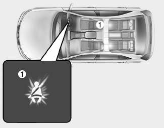
Seat belt warning light
Seat belt warning
Driver’s seat belt warning

■ Instrument cluster
As a reminder to the driver, the seat belt warning light will illuminate for approximately 6 seconds each time you turn the ignition switch ON regardless of belt fastening.
