Hyundai i-30: Rear Wiper/Washer / Rear Wiper Motor
Hyundai i30 (PD) 2018-2025 Service Manual / Body Electrical System / Rear Wiper/Washer / Rear Wiper Motor
Repair procedures
| Inspection |
Rear Wiper Motor
| 1. |
Remove the connector from the rear wiper motor.
|
| 2. |
Connect positive (+) battery cables to terminal 4 and negative (-) battery
cables to terminal 3 respectively.
|
| 3. |
Check that the motor operates normally. If they are abnormal, replace
the washer motor.
|
Automatic Stop Operation Check
| 1. |
Operate the motor at low speed using the stalk control.
|
| 2. |
Stop the motor operation anywhere except at the off position by disconnecting
the motor connector.
|
| 3. |
Connect the positive (+) lead from the battery to terminal 1 and the
negative (-) lead to terminal 3.
|
| 4. |
Connect the motor terminal 2 and terminal 4.
|
| 5. |
Check that the motor stops running at the off position.
|

| Inspection (With GDS) |
| 1. |
In the body electrical system, failure can be quickly diagnosed by using
the vehicle diagnostic system (GDS).
The diagnostic system(GDS) provides the following information.
|
| 2. |
Select the 'Car model' and the 'Body Control Module (BCM)' to be checked
in order to check the vehicle with the tester.
|
| 3. |
Select the 'Current Data' menu to search the current state of the input/output
data.
|

| Removal |
| 1. |
Remove the rear wiper arm & blade (B) after removing the nut and detaching
the wiper cap (A).
|
| 2. |
Remove the tailgate trim after opening the tailgate.
(Refer to Body - "Tailgate Trim")
|
| 3. |
Disconnect the rear wiper motor connector (A) and then remove the rear
wiper motor (B) after loosening bolts (3EA).
|
| Installation |
| 1. |
Install the rear wiper motor assembly.
|
| 2. |
Install the tailgate trim.
|
| 3. |
Install the rear wiper arm and rear wiper cap.
|
| 4. |
Set the rear wiper blade and to the lowest defogger heat line and tailgate
glass.
|

 Components and components location
Component Location
1. Rear wiper
arm & blade
2. Rear wiper arm nut
3. Rear wiper grommet
4. Rear wiper
motor assembly
5...
 Rear Washer Switch
Repair procedures
Inspection
Multifunction Switch Inspection
1.
Check for continuity between the terminals in each switch position as
shown below...
Other information:
Hyundai i30 (PD) 2018-2025 Owner's Manual: Where are the air bags?
Driver’s and passenger’s front air bags Your vehicle is equipped with a Supplemental Restraint System (SRS) and lap/shoulder belts at both the driver and passenger seating positions. The SRS consists of air bags which are located in the centre of the steering wheel, in the driver’s side lower crash pad below the steering wheel, and the passenger's side front panel pad above the glove box...
Hyundai i30 (PD) 2018-2025 Owner's Manual: Reverse parking aid function
When you move the shift lever to the R (Reverse) position, the outside rearview mirror(s) will rotate downwards to aid with driving in reverse. The position of the outside rearview mirror switch (1) determines whether or not the mirrors will move: Left/Right : When either the L (Left) or R (Right) switch is selected, both outside rearview mirrors will move...
Categories
- Manuals Home
- 3rd Generation i30 Owners Manual
- 3rd Generation i30 Service Manual
- Tyre pressure monitoring system
- Brake/clutch fluid
- Drive mode integrated control system
- New on site
- Most important about car
Tailgate
Opening the tailgate
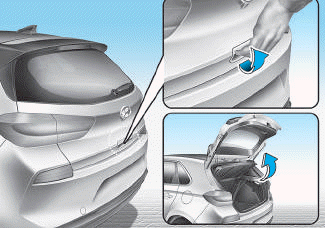
■ 5 Door, Wagon
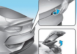
■ Fastback

Copyright © 2025 www.hi30.net