Hyundai i-30: Power Door Locks / Power Door Lock Switch
Hyundai i30 (PD) 2018-2025 Service Manual / Body Electrical System / Power Door Locks / Power Door Lock Switch
Schematic diagrams
| Circuit Diagram |

Repair procedures
| Removal |
| 1. |
Disconnect the negative (-) battery terminal.
|
| 2. |
Remove the center fascia panel.
(Refer to Body - "Center Fascia Panel")
|
| 3. |
Remove the crash pad garnish.
(Body - "Crash Pad Garnish")
|
| 4. |
Disconnect the door lock switch connector (A).
|
| 5. |
Remove the door lock switch (A) from the crash pad garnish after loosening
the screws.
|
| Inspection |
Power Door Lock Switch Inspection


Diagnosis with Diagnostic tool
| 1. |
In the body electrical system, failure can be quickly diagnosed by using
the vehicle diagnostic system (Diagnostic tool).
The diagnostic system (Diagnostic tool) provides the following information.
|
| 2. |
If diagnose the vehicle by Diagnostic tool, select "DTC Analysis" and
"Vehicle".
|
| 3. |
Select the 'Data Analysis' and 'Car model'.
|
| 4. |
Select the 'ICU' to search the current state of the input/output data.
|
| Installation |
| 1. |
Install the power window switch assembly.
|
| 2. |
Install the front door trim after connect the connector.
|
| 3. |
Connect the negative (-) battery terminal.
|
 Power Door Lock Module
Components and components location
Components
1. Door inside
handle cable
2. Door latch
assembly
Repair procedures
Inspection
•
When removing with a flat-tip screwdriver or remover, wrap protective
tape around the tools to prevent damage to components...
Other information:
Hyundai i30 (PD) 2018-2025 Owner's Manual: How does the air bags system operate?
The SRS consists of the following components: (1) Driver's front air bag module/ Driver’s knee air bag module (2) Passenger's front air bag module (3) Side air bag modules/ Side impact sensors (4) Curtain air bag modules (5) Rear Retractor pre-tensioner (6) Retractor pre-tensioner assemblies (7) Air bag warning light (8) SRS control module (SRSCM)/ Rollover sensor (9) Front impact sensors (10) Side pressure sensors (11) Passenger’s front air bag ON/OFF indicator (12) Passenger’s front air bag ON/OFF switch The SRSCM continually monitors all SRS components whilst the ignition switch is ON to determine if a crash impact is severe enough to require air bag deployment or pre-tensioner seat belt deployment...
Hyundai i30 (PD) 2018-2025 Service Manual: Front Disc Brake
Components and components location Components 1. Caliper body 2. Guide rod pin 3. Guide rod pin boot 4. Caliper carrier 5. Pad inner shim 6. Pad retainer 7. Brake pad 8. Pad return spring Repair procedures Removal 1...
Categories
- Manuals Home
- 3rd Generation i30 Owners Manual
- 3rd Generation i30 Service Manual
- FCA sensor
- Cruise control
- Trip computer
- New on site
- Most important about car
Warning light and message

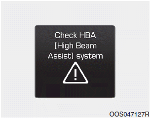
When the High Beam Assist (HBA)
System is not working properly, the
warning message will come on for a
few second. After the message disappears,
the master warning light ( )
will illuminate.
Copyright © 2025 www.hi30.net


