Hyundai i-30: Intake and Exhaust System / Intercooler
Components and components location
| Comoinents |
| 1. Intercooler
assembly 2. Intercooler air guard 3. Intercooler inlet hose & pipe 4. Intercooler outlet hose & pipe |
5. RCV solenoid
hose B 6. RCV solenoid hose C 7. RCV hose |
Repair procedures
| Removal and Installation |
| 1. |
Disconnect the battery negative terminal.
|
| 2. |
Remove the engine cover.
(Refer to Engine and Transaxle Assembly - "Engine Cover")
|
| 3. |
Remove the air duct and air cleaner assembly.
(Refer to Intake and Exhasut System - "Air Cleaner")
|
| 4. |
Remove the battery.
(Refer to Engine Electrical System - "Battery")
|
| 5. |
Remove the Engine Control Module (ECM).
(Refer to Engine Control/Fuel System - "Engine Control Module (ECM)")
|
| 6. |
Remove the battery tray.
(Refer to Engine Electrical System - "Battery")
|
| 7. |
Remove the engine room under cover.
(Refer to Engine and Transaxle Assembly - "Engine Room Under Cover")
|
| 8. |
Remove the intercooler inlet hose and pipe.
|


| 9. |
Remove the intercooler outlet hose and pipe.
|

| 10. |
Remove the front bumper cover.
(Refer to Body - "Front Bumper Cover")
|
| 11. |
Loosen the radiator air guard mounting bolts (A).
|
| 12. |
Remove the radiator lower air guard (A).
|
| 13. |
Remove the intercooler assembly (A).
|
| 14. |
Install in the reverse order of removal.
|
 Air Cleaner
Components and components location
Comoinents
1. Air cleaner
upper cover
2. Air cleaner element
3. Air cleaner body
4...
 Intake Manifold
Components and components location
Components
1. Intake manifold
2. Throttle body gasket
3. Throttle body
4. Vacuum pipe & hose assy
5...
Other information:
Hyundai i30 (PD) 2018-2025 Service Manual: Troubleshooting
Troubleshooting Error Item Failure symptom Inspection items Detailed inspections Relevant Parts/ Components Screen display TFT-LCD screen does not turn on 1) Connector attachments 2) Components 1) Check the connector attachments 2) Check B+, IGN and GND wiring 3) Check the components Connectors, wiring, fuses, dashboard Warning light Airbag warning lamp malfunction 1) Connector attachments 2) C-CAN 3) Components 1) Check airbag + signal (connectors) 2) Check C-CAN (ACU4) signal 3) Check the FPC attachment inside the dashboard ACU Connectors, wiring, fuses, dashboard Mode conversion Integrated driving mode malfunction 1) Connector attachments 2) Switch 3) Components 1) Check the switch input (connector) 2) Check the switch signal input (disconnection or shorting) 3) Check conversion with dashboard component Switch connector, wiring dashboard Illumination Interior light brightness cannot be controlled...
Hyundai i30 (PD) 2018-2025 Owner's Manual: Heating and air conditioning
1. Start the engine. 2. Set the mode to the desired position. To improve the effectiveness of heating and cooling, select: - Heating: - Cooling: 3. Set the temperature control to the desired position. 4. Set the air intake control to the outside (fresh) air position...
Categories
- Manuals Home
- 3rd Generation i30 Owners Manual
- 3rd Generation i30 Service Manual
- Cruise control
- Trip computer
- Exhaust System (DPF) Warning Light. Glow Indicator Light
- New on site
- Most important about car
Power windows
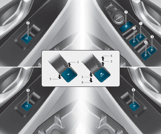
(1) Driver’s door power window
switch
(2) Front passenger’s door power
window switch
(3) Rear door (right) power window
switch
(4) Rear door (left) power window
switch
(5) Window opening and closing
(6) Automatic power window
(7) Power window lock switch

Copyright © 2025 www.hi30.net