Hyundai i-30: Body Electrical System / Immobilizer System
Hyundai i30 (PD) 2018-2025 Service Manual / Body Electrical System / Immobilizer System
 Auto Head Lamp Leveling Unit
Schematic diagrams
Circuit Diagram
Description and operation
Description
According to driving environment and loading state of vehicle, head lamp lighting
direction is changed to keep the driver's visibility range and to protect the
driver's vision from glare, aiming at safety driving...
Other information:
Hyundai i30 (PD) 2018-2025 Service Manual: Front Wheel Speed Sensor
Components and components location Components 1. Front wheel speed sensor 2. Front wheel speed sensor connector Repair procedures Removal 1. Loosen the wheel nuts slightly...
Hyundai i30 (PD) 2018-2025 Owner's Manual: Transmission shift indicator
Manual transmission shift indicator This indicator informs which gear is recommended whilst driving, to save fuel. Shifting up : ▲2, ▲3, ▲4, ▲5, ▲6 Shifting down :▼1, ▼2, ▼3, ▼4, ▼5 For example : Indicates that shifting up to the 3rd gear is recommended (currently the shift lever is in the 2nd or 1st gear)...
Categories
- Manuals Home
- 3rd Generation i30 Owners Manual
- 3rd Generation i30 Service Manual
- Shift-lock system. Shift-lock release
- Drive mode integrated control system
- Trip computer
- New on site
- Most important about car
Door locks
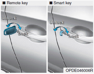
Operating door locks from outside the vehicle
Mechanical key

Turn the key toward the rear of the vehicle to unlock and toward the front of the vehicle to lock.
If you lock/unlock the driver's door with a key, a driver’s door will lock/unlock automatically.
Copyright © 2025 www.hi30.net

