Hyundai i-30: Auto Head Lamp Leveling Device / Auto Head Lamp Leveling Unit
Hyundai i30 (PD) 2018-2025 Service Manual / Body Electrical System / Auto Head Lamp Leveling Device / Auto Head Lamp Leveling Unit
Schematic diagrams
| Circuit Diagram |

Description and operation
| Description |
According to driving environment and loading state of vehicle, head lamp lighting
direction is changed to keep the driver's visibility range and to protect the
driver's vision from glare, aiming at safety driving.
Sensor integrated ECU mounting on the rear center arm drives the actuator mounting
on the head lamp since sensing the input signal following the vehicle's statically
changes.
Head lamp beam is automatically operated by chassis tilt.
| Operation |
Operating Procedure
| 1. |
Suspension angle change resulted from vehicle's load change.
|
| 2. |
Sensor angle change.
|
| 3. |
Microprocessor calculates necessary head lamp angle change amount.
|
| 4. |
Sending a proper signal to head lamp leveling device and driving actuator.
|
Operating Condition
| 1. |
Ignition on
|
| 2. |
Low beam on
|
| 3. |
On stop : If sensor lever change is 0.3° and above, head lamp is operated
after max. 1.5 sec.
|
| 4. |
On driving : If vehicle velocity is over 4km/h(2.48mile/h), velocity
change is not over 0.8-1.6km/h(0.5 - 1.0mile/h) per second, and loading
condition is changed, then head lamp is operated.
|
Components
| 1. |
Auto head lamp leveling unit
1. Leveling unit & sensor
2. Sensor mounting bracket
3. Sensor linkage
|

Repair procedures
| Inspection |
| 1. |
Ignition "ON".
|
| 2. |
Turn on the head lamp switch.
|
| 3. |
Check that the aim of the head lamp changes smoothly when the head lamp
leveling device switch is turned on.
|
| 4. |
If it does not operate well, check the connector and terminals to make
sure that they are connected.
If the terminals are bent, loose or corroded, repair them as necessary,
and recheck the system.
If the terminal is in good condition, move to the step 5.
|
| 5. |
Replace the head lamp assembly and check for proper operation.
|
| Removal |
| 1. |
Disconnect the negative (-) battery terminal.
|
| 2. |
Disconnect the head lamp leveling unit connector (A).
|
| 3. |
Remove the head lamp leveling unit (B) after loosening the mounting
bolts and nut.
|

| Installation |
| 1. |
Install the head lamp leveling unit.
|
| 2. |
Reconnect the head lamp leveling unit connector.
|
Troubleshooting
| Inspection with GDS |
Initialization and diagnosis sequence by using GDS equipment.
The following is the summarized A/S procedure.
|
No. |
Procedure |
|
1 |
Park the vehicle on level ground. |
|
2 |
Tire check |
|
3 |
IGN1 ON |
|
4 |
Head lamp Low Beam ON |
|
5 |
Connection with diagnostic tool |
|
6 |
Initial command by diagnostic tool |
|
7 |
Clear DTC Code |
|
8 |
IGN1 OFF → ON |
|
9 |
Re- Connection with diagnostic tool |
|
10 |
Checking of HLLD output value as 15% and DTC Code |
|
11 |
HLLD actuating by diagnostic tool command |
|
12 |
Head lamp mechanical Initial Aiming |
|

| 1. |
Select the vehicle model and "Auto Head Lamp Leveling System (AHLS)"
|
| 2. |
Check the sensor output value and data of each item on the system information
screen.
|

| 3. |
To perform functional test on AHLS outputs, select "Actuation Test".
|

| 4. |
Select " Parameter setting & Zero position Initial".
|


| 5. |
Confirm that AHLS operate forcefully in "Head lamp leveling" menu.
|


| 6. |
To check the DTC of the head lamp leveling system, select "Diagnostic
trouble codes"
|
 Components and components location
Component Location
1. Head lamp
leveling switch (Manual type only)
2. Head lamp leveling unit (Auto type only)
3...

Other information:
Hyundai i30 (PD) 2018-2025 Owner's Manual: Automatic reverse
If a window senses any obstacle whilst it is closing automatically, it will stop and lower approximately 30 cm (12 inches) to allow the object to be cleared. If the window detects the resistance whilst the power window switch is pulled up continuously, the window will stop upward movement then lower approximately 2...
Hyundai i30 (PD) 2018-2025 Service Manual: Passenger Airbag (PAB) Module
Components and components location Components 1. Passenger Air Bag (PAB) Description and operation Description The passenger airbag (PAB) is installed inside the crash pad and protects the front passenger in the event of a frontal crash...
Categories
- Manuals Home
- 3rd Generation i30 Owners Manual
- 3rd Generation i30 Service Manual
- Drive mode integrated control system
- FCA sensor
- Light bulbs
- New on site
- Most important about car
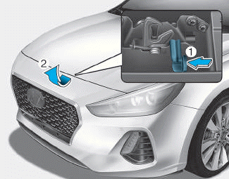
Bonnet
Opening the bonnet
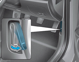
1. Park the vehicle and set the parking brake.
2. Pull the release lever to unlatch the bonnet. The bonnet should pop open slightly.

Copyright © 2025 www.hi30.net