Hyundai i-30: Power windows / Automatic reverse

If a window senses any obstacle whilst it is closing automatically, it will stop and lower approximately 30 cm (12 inches) to allow the object to be cleared.
If the window detects the resistance whilst the power window switch is pulled up continuously, the window will stop upward movement then lower approximately 2.5 cm (1 inch).
If the power window switch is pulled up continuously again within 5 seconds after the window is lowered by the automatic window reverse feature, the automatic window reverse will not operate.
Information
The automatic reverse feature is only active when the “Auto Up” feature is used by fully pulling up the switch to the second detent.
WARNING
Make sure body parts or other objects are safely out of the way before closing the windows to avoid injuries or vehicle damage.
Objects less than 4 mm (0.16 inch) in diameter caught between the window glass and the upper window channel may not be detected by the automatic reverse window and the window will not stop and reverse direction.
NOTICE
Do not install any accessories on the windows. The automatic reverse feature may not operate.
 Power windows
(1) Driver’s door power window
switch
(2) Front passenger’s door power
window switch
(3) Rear door (right) power window
switch
(4) Rear door (left) power window
switch
(5) Window opening and closing
(6) Automatic power window
(7) Power window lock switch
The ignition switch must be in the ON
position to be able to raise or lower
the windows...
 Power window lock switch
The driver can disable the power
window switches on the rear passengers'
doors by pressing the power
window lock switch.
When the power window lock switch
is pressed:
The driver's master control can
operate all the power windows...
Other information:
Hyundai i30 (PD) 2018-2025 Service Manual: Power Seat Control Switch
Schematic diagrams Circuit Diagram [Driver power seat switch] Repair procedures Inspection Seat Control Switch 1. With the power seat switch in each position, make sure that continuity exists between the terminals below...
Hyundai i30 (PD) 2018-2025 Service Manual: Emergency Fastening Device (EFD)
Components and components location Components 1. EFD (Emergency Fastening Device) System Description and operation Description The Emergency Fastening Device (EFD) operates at the same time with the Seat Belt Pretensioner when it satisifies the deployment condition after a collision...
Categories
- Manuals Home
- 3rd Generation i30 Owners Manual
- 3rd Generation i30 Service Manual
- Brake/clutch fluid
- EPB malfunction indicator
- Drive mode integrated control system
- New on site
- Most important about car
Tailgate
Opening the tailgate
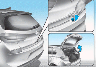
■ 5 Door, Wagon
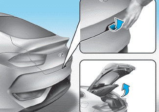
■ Fastback