Hyundai i-30: Maintenance / Tyres and wheels
WARNING
Tyre failure may cause loss of vehicle control resulting in an accident. To reduce risk of SERIOUS INJURY or DEATH, take the following precautions:
- Inspect your tyres monthly for proper inflation as well as wear and damage.
- The recommended cold tyre pressure for your vehicle can be found in this manual and on the tyre label located on the driver’s side centre pillar. Always use a tyre pressure gauge to measure tyre pressure. Tyres with too much or too little pressure wear unevenly causing poor handling.
- Check the pressure of the spare every time you check the pressure of the other tyres on your vehicle.
- Replace tyres that are worn, show uneven wear, or are damaged. Worn tyres can cause loss of braking effectiveness, steering control, or traction.
- ALWAYS replace tyres with the same size as each tyre that was originally supplied with this vehicle. Using tyres and wheels other than the recommended sizes could cause unusual handling characteristics, poor vehicle control, or negatively affect your vehicle’s Anti-Lock Brake System (ABS) resulting in a serious accident.
Tyre care
For proper maintenance, safety, and maximum fuel economy, you must always maintain recommended tyre inflation pressures and stay within the load limits and weight distribution recommended for your vehicle.

All specifications (sizes and pressures) can be found on a label attached to the driver’s side centre pillar.
- Recommended cold tyre inflation pressures
- Check tyre inflation pressure
- Tyre rotation
- Wheel alignment and tyre balance
- Tyre replacement
- Wheel replacement, Tyre traction & maintenance
- Tyre sidewall labelling
- Low aspect ratio tyres
 Battery
WARNING
To prevent SERIOUS INJURY or
DEATH to you or bystanders,
always follow these precautions
when working near or handling
the battery:
Always read and follow
instructions carefully
when handling a battery...
 Recommended cold tyre inflation
pressures
All tyre pressures (including the
spare) should be checked when the
tyres are cold. “Cold tyres” means
the vehicle has not been driven for at
least three hours or has been driven
for less than 1 mile (1...
Other information:
Hyundai i30 (PD) 2018-2025 Owner's Manual: Remote key precautions
The remote key will not work if any of the following occur: The key is in the ignition switch. You exceed the operating distance limit (about 30 m [90 feet]). The remote key battery is weak. Other vehicles or objects may be blocking the signal...
Hyundai i30 (PD) 2018-2025 Owner's Manual: To resume Smart Cruise Control set speed
If any method other than the cruise toggle switch was used to cancel cruising speed and the system is still activated, the cruising speed will automatically resume when you push the toggle switch up (RES+) or down (SET-). If you push the toggle switch up (RES+), the speed will resume to the recently set speed...
Categories
- Manuals Home
- 3rd Generation i30 Owners Manual
- 3rd Generation i30 Service Manual
- Cruise control
- Theft-alarm system
- Scheduled maintenance services
- New on site
- Most important about car
Panorama sunroof
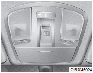
If your vehicle is equipped with a sunroof, you can slide or tilt your sunroof with the sunroof control lever located on the overhead console.

The ignition switch must be in the ON position before you can open or close the sunroof.
The sunroof can be operated for approximately 30 seconds after the ignition key is removed or turned to the ACC or LOCK(or OFF) position. However, if the front door is opened, the sunroof cannot be operated even within 30 seconds.
