Hyundai i-30: Body (Interior and Exterior) / Special service tools
Hyundai i30 (PD) 2018-2025 Service Manual / Body (Interior and Exterior) / Special service tools
| Special Service Tools |
|
Tool (Number and name) |
Illustration |
Use |
|
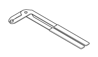
09880-4F000 Hog ring clip installer |
|
Hog ring clip installation |
 Specifications
Specifications
Items
Specification
Hood
Type
Rear hinged, stay rod type
Front Door
Construction
Front hinged, frame door construction
Regulator system
Wire drum type
Locking system
Pin-fork system
Rear Door
Construction
Front hinged, frame door construction
Regulator system
Wire drum type
Locking system
Pin-fork system
Tail Gate
Type
Front hinged, gas lifter type
Seat Belts
Front
3 point type with Emergency Locking Retractor (E...
 Troubleshooting
Troubleshooting
Symptom
Passible Cause
Remedy (Refer to page)
Water leaks from panorama sunroof
Deteriorated roof lid weatherstrip
Replace
Excessive roof lid-to-body clearance and improperly fitted weatherstrip
Adjust
Wind noise around Panorama sunroof
Loose or deformed deflector, gaps in body work
Retighten adjust or replace
Noise created by moving panorama sunroof lid
Foreign particles lodged in guide rail
Check drive cable and guide rails for foreign particles
Loose guide rails and lid
Retighten
Motor runs but sunroof does not move or moves only partially
Foreign particles lodged in guide rail
Adjust or replace
Incorrect engagement of motor pinion with drive cable
Decrease in motor's clutch slipping force
Increased sunroof sliding resistance or interference of sunroof with drive
cables, weatherstrip, etc...
Other information:
Hyundai i30 (PD) 2018-2025 Service Manual: Description and operation
Description Back view camera will activate when the backup light is ON with the ignition switch ON and the shift lever in the R position. This system is a supplemental system that shows behind the vehicle through the AV monitor or the ECM (Reverse Display Room Mirror) mirror while backing-up...
Hyundai i30 (PD) 2018-2025 Service Manual: Repair procedures
Removal 1. Disconnect the negative (-) battery terminal. 2. Remove the steering wheel. (Refer to Steering System - "Steering Wheel") 3. Remove the steering column upper and lower shrouds after loosening the screws...
Categories
- Manuals Home
- 3rd Generation i30 Owners Manual
- 3rd Generation i30 Service Manual
- Tyre pressure monitoring system
- EPB malfunction indicator
- To activate the ISG system
- New on site
- Most important about car
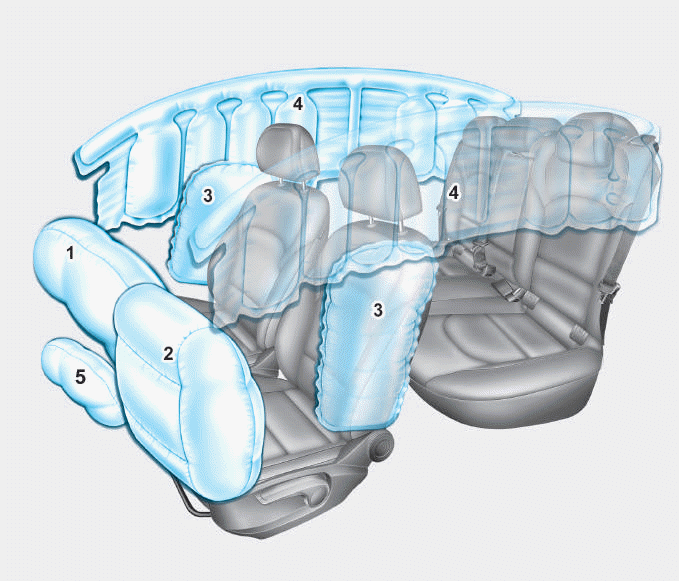
Air bag - supplemental restraint system

1. Driver’s front air bag
2. Passenger’s front air bag
3. Side air bag*
4. Curtain air bag*
5. Knee air bag*
6. Front passenger air bag ON/OFF
switch
Copyright © 2025 www.hi30.net

