Hyundai i-30: Controller / Heater & A/C Control Unit (DATC)
Hyundai i30 (PD) 2018-2025 Service Manual / Heating, Ventilation and Air Conditioning / Controller / Heater & A/C Control Unit (DATC)
Components and components location
| Components |

Connector [A]
|
Pin NO |
Function |
Pin NO |
Function |
|
1 |
Battery (+) |
21 |
IGN2 |
|
2 |
ISG B+ |
22 |
IGN1 |
|
3 |
ILL+ (TAIL) |
23 |
Blower motor (+) |
|
4 |
Sensor REF (+5V) |
24 |
Photo sensor_LH |
|
5 |
Mode actuator feedback |
25 |
Photo sensor_RH |
|
6 |
Temperature actuator feedback |
26 |
- |
|
7 |
Intake actuator feedback |
27 |
- |
|
8 |
EVAP Sensor (+) |
28 |
PTC Relay 3 |
|
9 |
AMB Sensor (+) |
29 |
PTC Relay 2 |
|
10 |
Mode actuator (Vent) |
30 |
PTC on signal |
|
11 |
Mode actuator (Defrost) |
31 |
Detent OUT (-) |
|
12 |
Temperature actuator (Cool) |
32 |
- |
|
13 |
Temperature actuator (Warm) |
33 |
C_CAN High |
|
14 |
Intake actuator (Fresh Air) |
34 |
C_CAN Low |
|
15 |
Intake actuator (Recirculated Air) |
35 |
Power mosfet (Drain feed back) |
|
16 |
HTD (Rear defog indicator) |
36 |
Power mosfet (Gate) |
|
17 |
Rear defog switch |
37 |
ECV + |
|
18 |
Clean signal |
38 |
ECV- (Ground) |
|
19 |
Ionizer diagnosis |
39 |
Sensor ground |
|
20 |
ILL- (RHEO) |
40 |
Ground |
Connector [B]
|
Pin NO |
Function |
Pin NO |
Function |
|
1 |
Passenger's temperature control actuator (Feedback) |
9 |
- |
|
2 |
Passenger's temperature control actuator (Cool) |
10 |
Duct sensor (+)_Vent |
|
3 |
Passenger's temperature control actuator (Warm) |
11 |
Duct sensor (-)_Floor |
|
4 |
Auto defogging (Feedback) |
12 |
Auto defogging sensor signal |
|
5 |
Auto defogging (Open) |
13 |
- |
|
6 |
Auto defogging (Off) |
14 |
- |
|
7 |
- |
15 |
- |
|
8 |
- |
16 |
Ground |
Repair procedures
| Self Diagnosis |
| 1. |
Self-diagnosis process.
|


| 2. |
Fault code display
|


| 3. |
If fault codes are displayed during the check, Inspect malfunction causes
by referring to fault codes.
|
| 4. |
Fail safe
|
| Replacement |
| 1. |
Disconnect the negative (-) battery terminal.
|
| 2. |
Remove the glove box upper cover assembly.
(Refer to Crash Pad - "Glove Box Upper Cover Assembly")
|
| 3. |
Remove the crash pad center lower cover (A) after loosening the mounting
screws.
|

| 4. |
After loosening the mounting screws, remove the A/C & heater controller
unit (A).
|

| 5. |
Disconnect the connector (A) and the air hose (B).
|

| 6. |
To install, reverse the removal procedure.
|

 Heater & A/C Control Unit (Manual)
Components and components location
Components
Connector [A]
Pin NO
Function
Pin NO
Function
1
Low
4
Middle Low
2
Common
5
Middle High
3
Ground
6
High
Connector [B]
Pin NO
Function
Pin NO
Function
1
Battery (+)
21
IGN2
2
ISG B+
22
IGN1
3
ILL+ (TAIL)
23
-
4
Sensor REF (+5V)
24
-
5
Mode actuator feedback
25
-
6
Temperature actuator feedback
26
-
7
Intake actuator feedback
27
MAX Blower ON Signal
8
EVAP Sensor (+)
28
PTC Relay 3
9
AMB Sensor (+)
29
PTC Relay 2
10
Mode actuator (Vent)
30
PTC on signal
11
Mode actuator (Defrost)
31
Detent OUT (-)
12
Temperature actuator (Cool)
32
-
13
Temperature actuator (Warm)
33
C_CAN High
14
Intake actuator (Fresh Air)
34
C_CAN Low
15
Intake actuator (Recirculated Air)
35
-
16
HTD (Rear defog indicator)
36
ECV +
17
Rear defog switch
37
ECV- (Ground)
18
-
38
Sensor ground
19
Blower ON signal to common
39
Ground
20
ILL- (RHEO)
40
Ground
Repair procedures
Replacement
1...

Other information:
Hyundai i30 (PD) 2018-2025 Service Manual: Rear Bumper Assembly
Components and components location Component Location 1. Rear bumper assembly Repair procedures Replacement • Put on gloves to prevent hand injuries...
Hyundai i30 (PD) 2018-2025 Service Manual: Canister
Repair procedures Removal 1. Turn the ignition switch OFF and disconnect the battery (-) terminal. 2. Disconnect the vapor hose quick-connectors (A). 3. Disconnect the vent hose quick-connector (B)...
Categories
- Manuals Home
- 3rd Generation i30 Owners Manual
- 3rd Generation i30 Service Manual
- To activate the ISG system
- Auto door lock/unlock features
- Front windscreen wiper service position
- New on site
- Most important about car
Door locks
Operating door locks from outside the vehicle
Mechanical key
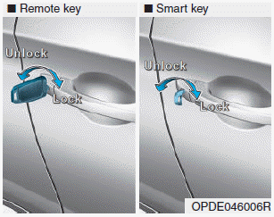
Turn the key toward the rear of the vehicle to unlock and toward the front of the vehicle to lock.
If you lock/unlock the driver's door with a key, a driver’s door will lock/unlock automatically.

Copyright © 2025 www.hi30.net