Hyundai i-30: Engine Control System / Heated Oxygen Sensor (HO2S)
Hyundai i30 (PD) 2018-2025 Service Manual / Engine Control / Fuel System / Engine Control System / Heated Oxygen Sensor (HO2S)
Description and operation
| Description |
Heated Oxygen Sensor (HO2S) consists of zirconium and alumina and is installed
both upstream and downstream of the Manifold Catalytic Converter. The sensor
output voltage varies in accordance with the air/fuel ratio.
The sensor must be hot in order to operate normally. To keep it hot, the sensor
has a heater which is controlled by the ECM via a duty cycle signal. When the
exhaust gas temperature is lower than the specified value, the heater warms
the sensor tip.

Specifications
| Specification |
HO2S [Bank 1 / Sensor 1] (Linear type)
|
Item |
Specification |
|
Heater Resistance (Ω) |
Approx. 2.5 [20°C (68°F)] |
HO2S [Bank 1 / Sensor 2] (Binary type)
|
Item |
Specification |
|
Heater Resistance (Ω) |
Approx. 3.0 [20°C (68°F)] |
Schematic diagrams
| Circuit Diagram |

Harness Connector
HO2S [Bank 1 / Sensor 1]

HO2S [Bank 1 / Sensor 2]

Repair procedures
| Inspection |
| 1. |
Turn the ignition switch OFF.
|
| 2. |
Disconnect the HO2S connector.
|
| 3. |
Measure resistance between the HO2S terminals 2 and 5 [B1/S1].
|
| 4. |
Measure resistance between the HO2S terminals 3 and 4 [B1/S2].
|
| 5. |
Check that the resistance is within the specification.
|
| Removal |
[Bank 1 / Sensor 1]
| 1. |
Turn the ignition switch OFF and disconnect the battery negative (-)
cable.
|
| 2. |
Disconnect the connector (A), and then remove the sensor (B).
|


[Bank 1 / Sensor 2]
| 1. |
Turn the ignition switch OFF and disconnect the battery negative (-)
cable.
|
| 2. |
Disconnect the connector (A), and then remove the sensor (B).
|


| Installation |
|

|
| 1. |
Install in the reverse order of removal.
|
 Knock Sensor (KS)
Description and operation
Description
Knocking is a phenomenon characterized by undesirable vibration and noise and
can cause engine damage...
 Accelerator Position Sensor (APS)
Description and operation
Description
Accelerator Position Sensor (APS) is installed on the accelerator pedal module
and detects the rotation angle of the accelerator pedal...
Other information:
Hyundai i30 (PD) 2018-2025 Service Manual: Components and components location
..
Hyundai i30 (PD) 2018-2025 Owner's Manual: Climate control additional features
Automatic ventilation To increase cabin air quality and reduce windscreen misting, air recirculation mode switches off automatically after about 5 to 30 minutes, depending on outside temperature, and the air intake will change to outside (fresh) mode...
Categories
- Manuals Home
- 3rd Generation i30 Owners Manual
- 3rd Generation i30 Service Manual
- Trip computer
- Battery replacement
- Cruise control
- New on site
- Most important about car
Power windows
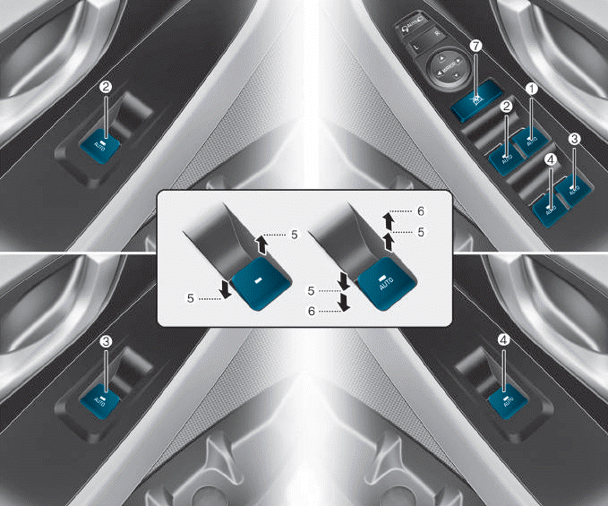
(1) Driver’s door power window
switch
(2) Front passenger’s door power
window switch
(3) Rear door (right) power window
switch
(4) Rear door (left) power window
switch
(5) Window opening and closing
(6) Automatic power window
(7) Power window lock switch

Copyright © 2025 www.hi30.net