Hyundai i-30: Engine Control System / Exhaust Gas Temperature Sensor (EGTS)
Hyundai i30 (PD) 2018-2025 Service Manual / Engine Control / Fuel System / Engine Control System / Exhaust Gas Temperature Sensor (EGTS)
Description and operation
| Description |
Exhaust Gas Temperature Sensor (EGTS) is installed on Gasoline Particulate Filter
(GPF) senses the temperature of exhaust gas flowing into. When pre-determined
engine condition is set, ECM burns soot gathered in GPF with exhaust gas. At
this time, the exhaust gas temperature is an important factor of engine condition
Exhaust Gas Temperature Sensor (EGTS) #1 (Front) [GPF Type]

Exhaust Gas Temperature Sensor (EGTS) #2 (Rear) [GPF Type]

Exhaust Gas Temperature Sensor (EGTS)

Specifications
| Specification |
Exhaust Gas Temperature Sensor (EGTS) #1, 2 [GPF Type]
▷ Type : Thermistor type
|
Temperature [°C (°F)] |
Resistance (kΩ) |
|
-40 (-40) |
0.17 |
|
0 (-32) |
0.201 |
|
100 (212) |
0.276 |
|
200 (392) |
0.35 |
|
300 (572) |
0.42 |
|
400 (752) |
0.489 |
|
500 (932) |
0.555 |
|
600 (1112) |
0.618 |
|
700 (1292) |
0.68 |
|
800 (1472) |
0.739 |
|
850 (1562) |
0.767 |
Exhaust Gas Temperature Sensor (EGTS)
▷ Type : Thermistor type
|
Temperature [°C (°F)] |
Resistance (kΩ) |
|
-40 (-40) |
120.1 - 140.6 |
|
-30 (-22) |
82.2 - 95.5 |
|
-20 (-4) |
57.9 - 66.8 |
|
-10 (14) |
41.8 - 47.9 |
|
0 (32) |
30.9 - 35.2 |
|
10 (50) |
23.3 - 26.4 |
|
20 (68) |
17.9 - 20.2 |
|
30 (86) |
14.0 - 15.7 |
|
40 (104) |
11.1 - 12.4 |
|
50 (122) |
8.92 - 9.91 |
|
60 (140) |
7.27 - 8.04 |
|
70 (158) |
5.99 - 6.60 |
|
80 (176) |
4.98 - 5.47 |
|
90 (194) |
4.19 - 4.58 |
|
100 (212) |
3.44 - 3.87 |
|
110 (230) |
3.03 - 3.29 |
|
120 (248) |
2.61 - 2.82 |
|
130 (266) |
2.26 - 2.44 |
|
140 (284) |
1.97 - 2.12 |
|
150 (302) |
1.73 - 1.85 |
|
160 (320) |
1.52 - 1.63 |
|
170 (338) |
1.35 - 1.44 |
|
180 (356) |
1.08 - 1.15 |
|
190 (374) |
1.07 - 1.14 |
|
200 (392) |
0.97 - 1.03 |
|
210 (410) |
0.86 - 0.93 |
|
220 (428) |
0.79 - 0.85 |
|
230 (446) |
0.72 - 0.77 |
|
240 (464) |
0.66 - 0.71 |
|
250 (482) |
0.60 - 0.65 |
|
260 (500) |
0.55 - 0.60 |
|
270 (518) |
0.51 - 0.55 |
|
280 (536) |
0.47 - 0.51 |
|
290 (554) |
0.44 - 0.47 |
|
300 (572) |
0.40 - 0.43 |
Schematic diagrams
| Circuit Diagram |
Exhaust Gas Temperature Sensor (EGTS) #1 (Front) [GPF Type]

Harness Connector

Exhaust Gas Temperature Sensor (EGTS) #2 (Rear) [GPF Type]

Harness Connector

Exhaust Gas Temperature Sensor (EGTS)

Harness Connector

Repair procedures
| Inspection |
| 1. |
Turn ignition switch OFF.
|
| 2. |
Disconnect the connector of exhaust gas temperature sensors.
|
| 3. |
Measure resistance between sensor signal terminal and ground terminal.
|
| 4. |
Check that the resistance is within the specification.
|
| Removal |
Exhaust Gas Temperature Sensor (EGTS) #1 (Front) [GPF Type]
| 1. |
Turn the ignition switch OFF and disconnect the battery negative (-)
terminal.
|
| 2. |
Lift up the vehicle.
|
| 3. |
Remove the floor under cover.
|
| 4. |
Disconnect the egts connector (A).
|
| 5. |
Remove the egts sensor (A).
|
Exhaust Gas Temperature Sensor (EGTS) #2 (Rear) [GPF Type]
| 1. |
Turn the ignition switch OFF and disconnect the battery negative (-)
terminal.
|
| 2. |
Lift up the vehicle.
|
| 3. |
Remove the floor under cover.
|
| 4. |
Disconnect the egts connector (A).
|
| 5. |
Remove the egts sensor (A).
|
Exhaust Gas Temperature Sensor (EGTS)
| 1. |
Turn the ignition switch OFF and disconnect the battery negative (-)
terminal.
|
| 2. |
Remove the front muffler heat protector (A).
|
| 3. |
Disconnect the egts connector (A).
|
| 4. |
Remove the egts sensor (B).
|
| Installation |
|
| 1. |
Install in the reverse order of removal.
|
 Differential Pressure Sensor (DPS)
Description and operation
Description
Differential Pressure Sensor (DPS) is measure the pressure difference of EGR
inlet and outlet...
 Differential Pressure Valve (DPV)
Description and operation
Description
Differential pressure valve (DPV) is control the pressure difference of EGR
inlet and outlet...
Other information:
Hyundai i30 (PD) 2018-2025 Service Manual: Description and operation
Safety Function of Power Window When driver door power window auto-up switch is operated, safety function is activated. 1. Safety function condition When the force of 100N (using the 10N/mm spring) is detected while the window is rising, the window is pulled down...
Hyundai i30 (PD) 2018-2025 Service Manual: Components and components location
..
Categories
- Manuals Home
- 3rd Generation i30 Owners Manual
- 3rd Generation i30 Service Manual
- Jump starting procedure
- Exhaust System (DPF) Warning Light. Glow Indicator Light
- Theft-alarm system
- New on site
- Most important about car
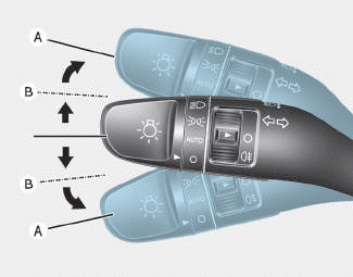
Turn signals and lane change signals

To signal a turn, push down on the lever for a left turn or up for a right turn in position (A). To signal a lane change, move the turn signal lever slightly and hold it in position (B).The lever will return to the OFF position when released or when the turn is completed.
Copyright © 2025 www.hi30.net


