Hyundai i-30: Engine and Transaxle Assembly / Engine Mounting
Hyundai i30 (PD) 2018-2025 Service Manual / Engine Mechanical System / Engine and Transaxle Assembly / Engine Mounting
Components and components location
| Components |

| 1. Transaxle
mounting bracket 2. Roll rod bracket |
3. Engine mounting
bracket 4. Engine mounting support bracket |
Repair procedures
| Removal and Installation |
Roll Rod Bracket
| 1. |
Remove the engine room under cover.
(Refer to Engine and Transaxle Assembly - "Engine Room Under Cover")
|
| 2. |
Remove the roll rod bracket (A).
|

| 3. |
Remove the roll rod mounting support bracket (A).
|

| 4. |
Install in the reverse order of removal.
|
Engine Mounting Bracket
| 1. |
Remove the engine room under cover.
(Refer to Engine and Transaxle Assembly - "Engine Room Under Cover")
|
| 2. |
Install the jack to the edge of oil pan to support the engine.
|

| 3. |
Remove the engine mounting support bracket (A).
|

| 4. |
Remove the reservoir tank.
(Refer to Cooling System - "Reservoir Tank")
|
| 5. |
Remove the engine mounting bracket (A).
|

| 6. |
Install in the reverse order of removal.
|
Transaxle Mounting Bracket
| 1. |
Remove the air duct and air cleaner assembly.
(Refer to Intake and Exhasut System - "Air Cleaner")
|
| 2. |
Remove the battery.
(Refer to Engine Electrical System - "Battery")
|
| 3. |
Remove the engine control module (ECM).
(Refer to Engine Control / Fuel System - "Engine Control Module (ECM)")
|
| 4. |
Remove the battery tray.
(Refer to Engine Electrical System - "Battery")
|
| 5. |
Remove the engine room under cover.
(Refer to Engine and Transaxle Assembly - "Engine Room Under Cover")
|
| 6. |
Install the jack under the transaxle to support it.
|
| 7. |
Remove the front wheel guard.
(Refer to Body - "Body Side Molding")
|
| 8. |
Remove the service cover (A).
|

| 9. |
Remove the transaxle support bracket mounting bolts (A).
|

| 10. |
Remove the transaxle mounting bracket (A).
|

| 11. |
Install in the reverse order of removal.
|
 Engine Room Under Cover
Repair procedures
Removal and installation
1.
Remove the engine room under cover (A).
Tightening torque :
3...
 Engine and Transaxle Assembly
Repair procedures
Removal
•
Use fender covers to avoid damaging painted surfaces...
Other information:
Hyundai i30 (PD) 2018-2025 Owner's Manual: Luggage rail system (wagon)
The luggage rail system may help prevent the luggage from rolling around in the luggage compartment. Build in segmentation bar Put both pillars (A) of the segmentation bar on the rail openings. To move the segmentation bar, push the lever (B)...
Hyundai i30 (PD) 2018-2025 Service Manual: Audio Unit
Components and components location Components Audio Connector Pin Information NO Connector A Connector B 1 Rear left speaker (+) - 2 Front left speaker (+) - 3 Front right speaker (+) - 4 Rear right speaker (+) Steering wheel key 5 - - 6 Door open USB data (HI) 7 IGN 1 USB VCC 8 ILL (+) - 9 DETENT - 10 Rear left speaker (-) MIC signal (+) 11 Front left speaker (-) ACC 12 Front right speaker (-) Battery (+) 13 Rear right speaker (-) - 14 - - 15 - - 16 - Speed 17 ILL (-) Steering wheel key GND 18 Antenna Power USB data (LOW) 19 USB GND 20 - 21 - 22 MIC signal (-) 23 - 24 GND Display Audio Connector Pin Information No Connector A Connector B 1 Rear door speaker (Left +) - 2 Rear door speaker (Left -) Mic_Signal (+) 3 USB Ground - 4 USB Data_High - 5 USB Data_Low Antenna power 6 USB_VCC Illumination (+) 7 Camera video MM CAN (High) 8 - - 9 - - 10 AUX Audio R Battery (+) 11 AUX Detect Battery (+) 12 Steering wheel remote Ground 13 Front door speaker (Left +) Ground 14 Front door speaker (Left -) Mic_Ground 15 Front door speaker (Right -) Mic_Signal (-) 16 Front door speaker (Right +) - 17 - - 18 - Vehicle speed 19 - Illumination (-) 20 Camera power ground MM CAN (Low) 21 Camera video ground - 22 - ACC 23 - - 24 AUX Audio L - 25 AUX Audio ground - 26 Steering wheel remote grond Door open 27 Rear door speaker (Right -) - 28 Rear door speaker (Right +) - 29 - - 30 - - 31 - - 32 Camera power ground IGN 1 33 Camera shield ground - 34 - - 35 - - 36 Camera_Detect 37 - 38 - Repair procedures Removal • When removing with a flat-tip screwdriver or remover, wrap protective tape around the tools to prevent damage to components...
Categories
- Manuals Home
- 3rd Generation i30 Owners Manual
- 3rd Generation i30 Service Manual
- Exhaust System (DPF) Warning Light. Glow Indicator Light
- Jump starting procedure
- Auto door lock/unlock features
- New on site
- Most important about car
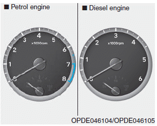
Gauges and meters
Speedometer
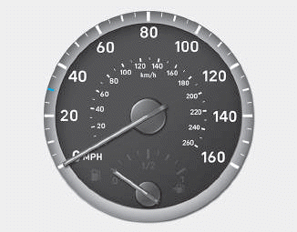
The speedometer indicates the speed of the vehicle and is calibrated in kilometers per hour (km/h) and/or miles per hour (MPH).
Tachometer

Copyright © 2025 www.hi30.net