Hyundai i-30: Rear Suspension System / Trailing Arm
Repair procedures
| Removal |
| 1. |
Loosen the wheel nuts slightly.
Raise the vehicle, and make sure it is securelysupported.
|
| 2. |
Remove the rear wheel and tire (A) from the rearhub.
|
| 3. |
Loosen the trailing arm mounting nuts (A), and thenremove the trailing
arm.
|
| 4. |
Remove the parking brake cable fromt the rearcaliper.
(Refer to Brake System - "Rear Disc Brake")
|
| 5. |
Loosen the wheel speed sensor cable bracket nutand then separate the
cables with the trailing arm.
|
| 6. |
Disconnect the connector (A) and then remove thehead lamp leveling unit
(B) after loosening themounting bolt.
|
| 7. |
Loosen the mounting bolt and then remove thetrailing arm from the frame.
|
| 8. |
Installation in the reverse of removal.
|
 Rear Assist Arm
Repair procedures
Removal
1.
Loosen the wheel nuts slightly.
Raise the vehicle, and make sure it is securelysupported...
 Rear Coil Spring
Repair procedures
Removal
1.
Loosen the wheel nuts slightly.
Raise the vehicle, and make sure it is securelysupported...
Other information:
Hyundai i30 (PD) 2018-2025 Service Manual: Rear Seat Back Cover
Components and components location Component Location 1. Rear seat back cover [LH] 2. Rear seat back cover [RH] Repair procedures Replacement [LH] • Put on gloves to prevent hand injuries...
Hyundai i30 (PD) 2018-2025 Service Manual: Rear torsion beam axle
Components and components location Components 1. Torsion beam axle Repair procedures Removal 1. Loosen the wheel nuts slightly. Raise the vehicle, and make sure it is securely supported...
Categories
- Manuals Home
- 3rd Generation i30 Owners Manual
- 3rd Generation i30 Service Manual
- Light bulbs
- EPB malfunction indicator
- FCA sensor
- New on site
- Most important about car
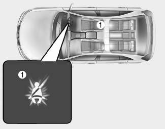
Seat belt warning light
Seat belt warning
Driver’s seat belt warning

■ Instrument cluster
As a reminder to the driver, the seat belt warning light will illuminate for approximately 6 seconds each time you turn the ignition switch ON regardless of belt fastening.
Copyright © 2025 www.hi30.net


