Hyundai i-30: Tires/Wheels / Tire
Repair procedures
| Tire Wear |
| 1. |
Measure the tread depth of the tires.
|
| 2. |
If the remaining tread depth (A) is less than the limit, replace the
tire.
|


| Removal |
| 1. |
Remove valve core and deflate the tire.
|
| 2. |
Remove the side of the tire bead area from the wheel using tire changing
machine.
|

| 3. |
Rotate the wheel clockwise.
|


| Installation |
| 1. |
Apply tire soap or lubrication to the top and bottom tire beads.
|

| 2. |
To fit the bottom bead, position the valve at the 5 o’clock position
relative to the head on the tire changing machine.
|

| 3. |
Place the tire on the rim so the bottom bead touches the edge of the
rim after the valve (6 o’clock). Rotate the rim clockwise, and push
down on the tire at the 3 o’clock position to fit bottom bead.
|

| 4. |
After bottom bead is on tire, rotate the rim until the valve is at the
5 o’clock position relative to the head on the tire changing machine.
Push down on the tire at the 3 o’clock position and rotate the rim clockwise
to fit the top bead.
|

| 5. |
Inflate the tire until both beads seat.
|
|||||||||||||||||||||||||||||||||||||||||||||

| Adjustment |
If the steering pulls to one side, rotate the tires according to the following
wheel rotation procedure.
| 1. |
Rotate the front right and front left tires, and perform a road test
in order to confirm vehicle stability.
|

| 2. |
If the steering pulls to the opposite side, rotate the front and rear
tires, and perform a road test again.
|

| 3. |
If the steering continues to pull to one side, rotate the front right
and left tires again, and perform a road test.
|
| 4. |
If the steering continues to pull to the opposite side, replace the
front wheels with new ones.
|

 Tires/Wheels
..
 Wheel
Wheel
Repair procedures
Hub nut tightening sequence
1.
Tighten the hub nuts as follows.
Tightening torque :
107...
Other information:
Hyundai i30 (PD) 2018-2025 Owner's Manual: Remote key precautions
The remote key will not work if any of the following occur: The key is in the ignition switch. You exceed the operating distance limit (about 30 m [90 feet]). The remote key battery is weak. Other vehicles or objects may be blocking the signal...
Hyundai i30 (PD) 2018-2025 Service Manual: Front Seat Shield Outer Cover
Components and components location Component Location 1. Front seat shield outer cover Repair procedures Replacement • Put on gloves to prevent hand injuries...
Categories
- Manuals Home
- 3rd Generation i30 Owners Manual
- 3rd Generation i30 Service Manual
- Theft-alarm system
- Engine coolant
- Drive mode integrated control system
- New on site
- Most important about car
Tailgate
Opening the tailgate
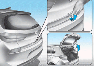
■ 5 Door, Wagon
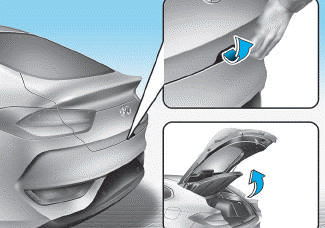
■ Fastback

Copyright © 2025 www.hi30.net