Hyundai i-30: Idle stop and go (ISG) system / The battery sensor deactivation

Hyundai i30 (PD) 2018-2024 Owner's Manual / Driving your vehicle / Idle stop and go (ISG) system / The battery sensor deactivation

Hyundai i30. The battery sensor deactivation

The battery sensor is deactivated, when the battery is disconnected from the negative pole for maintenance purpose.

In this case, the ISG system is limitedly operated due to the battery sensor deactivation. Thus, the driver needs to take the following procedures to reactivate the battery sensor after disconnecting the battery.

Prerequisites to reactivate the battery sensor

Keep the engine in the OFF status for 4 hours, and attempt to restart the engine 3 to 4 times for the batterysensor reactivation.

Pay extreme caution not to connect any accessories (i.e. navigation and black box) to the vehicle with the engine in the OFF status. If not, the battery sensor may not be reactivated.

Information

The ISG system may not operate in the following situations.

- There is a malfunction with the ISG system.
- The battery is weak.
- The brake vacuum pressure is low. In those cases, we recommend that you have the ISG system checked by a HYUNDAI authorised repairer.

NOTICE

  • Use only the genuine HYUNDAI ISG battery for replacement. If not, the ISG system may not normally operate.
  • Do not recharge the ISG battery with a general battery charger. If not, it may damage or explode the ISG battery.
  • Do not remove the battery cap. If not, the battery electrolyte, which is harmful to the human body, may leak out.

    To deactivate the ISG system, ISG system malfunction

    To deactivate the ISG system Press the ISG OFF button to deactivate the ISG system. Then, the ISG OFF button indicator illuminates, and the message "Auto Stop System Off" appears on the LCD display...

    Drive mode integrated control system

    The drive mode may be selected according to the driver's preference or road condition. The system resets to be in the NORMAL mode (except if it is in ECO mode), when the engine is restarted...

    Other information:

    Hyundai i30 (PD) 2018-2024 Service Manual: Smart Key Diagnostic


    Repair procedures Inspection Self Diagnosis With Scan Tool It will be able to diagnose defects of SMART KEY system with Diagnostic tool quickly. Diagnostic tool can operates actuator forcefully, input/output value monitoring and self diagnosis...

    Hyundai i30 (PD) 2018-2024 Service Manual: Engine Control Module (ECM)


    Schematic diagrams ECM Terminal and Input / Output signal ECM Harness Connector ECM Terminal Function Connector [A] Terminal Description 1 Fuel Pressure Regulator Valve (FPRV) [High] Control 2 Integrated Thermal Management Module (ITM) Motor (+) 3 Integrated Thermal Management Module (ITM) Motor (-) 4 Exhaust Gas Temperature Sensor (EGTS) #2 (T4) Ground [GPF Type] 5 Engine Coolant Temperature Sensor (ECTS) #1 Ground 6 - 7 Engine Coolant Temperature Sensor (ECTS) #2 Ground 8 Differential Pressure Valve (DPV) Ground 9 Rail Pressure Sensor (RPS) Ground 10 Exhaust Gas Temperature Sensor (EGTS) Ground 11 Manifold Absolute Pressure Sensor (MAPS) Ground 12 Electric Waste Gate Control Actuator (EWGA) Ground 13 EGR Pressure Sensor Ground 14 Oil Pressure & Temperature Sensors (OPTS) Ground 15 Electric Exhaust Gas Recirculation (EEGR) Control Valve Ground 16 - 17 A/C Pressure Transducer (APT) Ground 18 Sensor Power (+5V) (Camshaft Position Sensor (CMPS) [Bank 1 / Intake, Exhaust]) 19 Sensor Power (+5V) (Manifold Absolute Pressure Sensor (MAPS)) Sensor Power (+5V) (Electric Exhaust Gas Recirculation (EEGR)) Sensor Power (+5V) (Crankshaft Position Sensor (CKPS)) 20 Sensor Power (+5V) (Oil Pressure & Temperature Sensors (OPTS)) Sensor Power (+5V) (Electric Throttle Control Module (ETC)) Sensor Power (+5V) (Rail Pressure Sensor (RPS)) 21 Throttle Position Sensor (TPS) Ground 22 Electric Exhaust Gas Recirculation (EEGR) Control Valve Motor (+) 23 Electric Exhaust Gas Recirculation (EEGR) Control Valve Motor (-) 24 Knock Sensor (KS ) Shield Ground 25 - 26 Ignition Coil (Cylider #3) Control 27 - 28 - 29 Exhaust Gas Temperature Sensor (EGTS) #1 (T3) Ground [GPF Type] 30 - 31 - 32 - 33 EGR Pressure Sensor Signal 34 - 35 Integrated Thermal Management Module (ITM) Motor Ground 36 - 37 Camshaft Position Sensor (CMPS) [Bank 1 / Intake] Signal 38 - 39 Electric Waste Gate Control Actuator (EWGA) Signal 40 Sensor Power (+5V) (EGR Pressure Sensor) Sensor Power (+5V) (Electric Waste Gate Control Actuator (EWGA)) 41 Sensor Power (+5V) (Accelerator Position Sensor (APS #1)) 42 Sensor Power (+5V) (Brake Booster Vacuum Pressure Sensor (BBVPS)) Sensor Power (+5V) (A/C Pressure Transducer (APT)) 43 Injector (Cylinder #3) [+] Control 44 Injector (Cylinder #2) [+] Control 45 - 46 - 47 CCP-CAN [High] 48 Ignition Coil (Cylinder #1) Control 49 - 50 Neutral Switch [With ISG] 51 - 52 - 53 - 54 Exhaust Gas Temperature Sensor (EGTS) #1 (T3) Signal [GPF Type] 55 - 56 Exhaust Gas Temperature Sensor (EGTS) #2 (T4) Signal [GPF Type] 57 - 58 Differential Pressure Sensor (DPS) Signal 59 Exhaust Gas Temperature Sensor (EGTS) Signal 60 Camshaft Position Sensor (CMPS) [Bank 1 / Exhaust] Ground 61 Mass Air Flow Sensor (MAFS) Signal 62 - 63 Engine Speed Signal Output 64 Injector (Cylinder #1) [+] Control 65 Injector (Cylinder #4) [+] Control 66 Injector (Cylinder #3) [-] Control 67 Injector (Cylinder #4) [-] Control 68 Ignition Coil (Cylider #2) Control 69 CCP-CAN [Low] 70 Camshaft Position Sensor (CMPS) [Bank 1 / Exhaust] Signal 71 Crankshaft Position Sensor (CKPS) Ground 72 Ignition Lock Switch [M/T & Without Smart Key] 73 Oil Pressure Sensor (OPS) Signal 74 Intake Air Temperature Sensor (IATS) Signal 75 Engine Coolant Temperature Sensor (ECTS) #1 Signal 76 Engine Coolant Temperature Sensor (ECTS) #2 Signal 77 Electric Exhaust Gas Recirculation (EEGR) Control Valve Signal 78 Differential Pressure Valve (DPV) Signal 79 Throttle Position Sensor (TPS) #2 Signal 80 Rail Pressure Sensor (RPS) Signal 81 - 82 Integrated Thermal Management Module (ITM) Motor Signal 83 Mass Air Flow Sensor (MAFS) Ground 84 A/C Pressure Transducer (APT) Signal 85 - 86 Injector (Cylinder #2) [-] Control 87 Injector (Cylinder #1) [-] Control 88 Fuel Pressure Regulator Valve (FPRV) [Low] Control 89 Differential Pressure Sensor (DPS) Ground 90 Ignition Coil (Cylinder #4) Control 91 Crankshaft Position Sensor (CKPS) Signal 92 - 93 Heated Oxygen Sensor (HO2S) [Bank 1 / Sensor 2] Ground 94 - 95 Heated Oxygen Sensor (HO2S) [Bank 1 / Sensor 2] Signal 96 - 97 Oil Temperature Sensor (OTS) Signal 98 Throttle Position Sensor (TPS) #1 Signal 99 - 100 - 101 Manifold Absolute Pressure Sensor (MAPS) Signal 102 Camshaft Position Sensor (CMPS) [Bank 1/Intake] Ground 103 - 104 Knock Sensor (KS) Signal 105 Knock Sensor (KS) Ground Connector [B] Terminal Description 1 Chassis Ground 2 Chassis Ground 3 Battery Power (B+) (Battery) 4 Chassis Ground 5 Battery Power (B+) (Main Relay) 6 Battery Power (B+) (Main Relay) 7 - 8 - 9 Sensor Power (+5V) (Integrated Thermal Management Module (ITM) Motor) Sensor Power (+5V) (Mass Air Flow Sensor (MAFS)) 10 Sensor Power (+5V) (Accelerator Position Sensor (APS) #2) 11 Boost Pressure Sensor (BPS) Signal Input 12 Accelerator Position Sensor (APS) #2 Ground 13 Accelerator Position Sensor (APS) #1 Ground 14 Brake Booster Vacuum Pressure Sensor (BBVPS) Ground [With ISG] 15 - 16 Boost Pressure Sensor (BPS) Ground 17 Fuel Level Sender (FLS) Signal 18 Accelerator Position Sensor (APS #2) Signal 19 - 20 - 21 - 22 RCV Control Solenoid Valve Control 23 Cooling Fan Relay [PWM] Control 24 Electric Waste Gate Control Actuator (EWGA) DC Motor (+) Control 25 Electric Waste Gate Control Actuator (EWGA) DC Motor (-) Control 26 Ignition Switch Signal Input 27 Sensor Power (+5V) (Differential Pressure Sensor (DPS)) Sensor Power (+5V) (Differential Pressure Valve (DPV)) Sensor Power (+5V) (Boost Pressure Sensor (BPS)) 28 - 29 - 30 Brake Light Switch Signal Input 31 Brake Test Switch Signal Input 32 Accelerator Position Sensor (APS #1) Signal 33 - 34 ISG OFF Switch Signal Input [With ISG] 35 Start Signal Input 36 - 37 Fuel Pump Relay Control [W/O Smart Key] 38 DC/DC Converter (LDC) Control [With ISG] 39 - 40 Variable Oil Pump Valve Control 41 ETC Motor [+] Control 42 ETC Motor [-] Control 43 - 44 LIN communication signal input 45 C-CAN (Low) 46 - 47 - 48 Clutch Switch [M/T] 49 Wiper Switch Signal Input 50 Blower Motor MAX Input 51 Start Relay Control (Low Side) 52 - 53 - 54 Rear Defrost Switch Signal Input 55 - 56 - 57 - 58 Differential Pressure Valve (DPV) DC Motor (+) Control 59 Differential Pressure Valve (DPV) DC Motor (-) Control 60 Battery Power (B+) (Battery) 61 LIN Communication Signal input 62 C-CAN (High) 63 Brake Booster Vacuum Pressure Sensor (BBVPS) Signal [With ISG] 64 Heated Oxygen Sensor (HO2S) [Bank 1 / Sensor 1] VS+ (NERNST Cell Voltage) 65 Heated Oxygen Sensor (HO2S) [Bank 1 / Sensor 1] Rc (Compensative Resistance) 66 Heated Oxygen Sensor (HO2S) [Bank 1 / Sensor 1] Rc/Rp (Pump Cell Voltage) 67 Heated Oxygen Sensor (HO2S) [Bank 1 / Sensor 1] VS-/IP- (Common Ground for VS, IP) 68 - 69 A/C Compressor Relay Control 70 - 71 Start Relay Control (High side) 72 - 73 - 74 Engine Control Relay Control 75 Heated Oxygen Sensor (HO2S) [Bank 1 / Sensor 1] Heater Control 76 Heated Oxygen Sensor (HO2S) [Bank 1 / Sensor 2] Heater Control 77 Vehicle Speed Signal Input 78 CCP-CAN [High] 79 CCP-CAN [Low] 80 - 81 - 82 - 83 Purge Control Solenoid Valve (PCSV) Control 84 Fuel Pump Relay Control [With Smart Key] 85 ISG OFF Switch (IND...

    Categories

    Panorama sunroof

    If your vehicle is equipped with a sunroof, you can slide or tilt your sunroof with the sunroof control lever located on the overhead console.

    Hyundai i30. Panorama sunroof

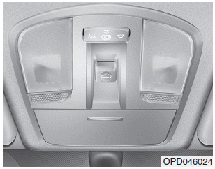
    The ignition switch must be in the ON position before you can open or close the sunroof.

    The sunroof can be operated for approximately 30 seconds after the ignition key is removed or turned to the ACC or LOCK(or OFF) position. However, if the front door is opened, the sunroof cannot be operated even within 30 seconds.

    read more


    Copyright © 2024 www.hi30.net