Hyundai i-30: Forward collision-avoidance assist (FCA) system - sensor fusion type (front radar + front camera) / System malfunction

Check FCA (Forward Collision Avoidance Asst.)
- When the FCA is not working properly,
the FCA warning light (
 )
will illuminate and the warning
message will appear for a few seconds.
After the message disappears,
the master warning light
(
)
will illuminate and the warning
message will appear for a few seconds.
After the message disappears,
the master warning light
( ) will illuminate. In this
case, we
recommend that you have the vehicle
inspected by a HYUNDAI
authorised repairer.
) will illuminate. In this
case, we
recommend that you have the vehicle
inspected by a HYUNDAI
authorised repairer. - The FCA warning message may appear along with the illumination of the ESC (Electronic Stability Control) warning light.
WARNING
- The FCA is only a supplemental system for the driver's convenience. The driver should hold the responsibility to control the vehicle operation. Do not solely depend on the FCA system. Rather, maintain a safe braking distance, and, if necessary, depress the brake pedal to reduce the driving speed.
- In certain instances and under certain driving conditions, the FCA system may activate unintentionally. This initial warning message appears on the LCD display with a warning chime. Also, in certain instances the front radar sensor or camera recognition system may not detect the vehicle or pedestrian ahead. The FCA system may not activate and the warning message will not be displayed.
- Even if there is any problem with the brake control function of the FCA system, the vehicle’s basic braking performance will operate normally. However, brake control function for avoiding collision will not activate.
- If the vehicle in front stops suddenly, you may have less control of the brake system. Therefore, always keep a safe distance between your vehicle and the vehicle in front of you.
- The FCA system may activate during braking and the vehicle may stop suddenly shifting loose objects toward the passengers. Always keep loose objects secured.
- The FCA system may not activate if the driver applies the brake pedal to avoid a collision.
- The FCA system may not activate according to the road conditions, inclement weather, driving conditions or traffic conditions.
- The brake control may be insufficient, possibly causing a collision, if a vehicle in front abruptly stops. Always pay extreme caution.
- Occupants may get injured, if the vehicle abruptly stops by the activated FCA system. Pay extreme caution.
WARNING
- The FCA system does not operate when the vehicle is in reverse.
- The FCA system is not designed to detect other objects on the road such as animals.
- The FCA system does not detect vehicles in the opposite lane.
- The FCA system does not detect cross traffic vehicles that are approaching.
- The FCA system cannot detect the driver approaching the side view of a parked vehicle (for example on a dead end street.)
In these cases, you must maintain a safe braking distance, and if necessary, depress the brake pedal to reduce the driving speed in order to maintain a safe distance.
 FCA sensor
■ Front radar
■ Front camera
In order for the FCA system to operate
properly, always make sure the
sensor cover or sensor is clean and
free of dirt, snow, and debris...
 Limitations of the system
The Forward Collision avoidance
assist (FCA) system system is
designed to monitor the vehicle
ahead or a pedestrian in the roadway
through radar signals and camera
recognition to warn the driver that a
collision is imminent, and if necessary,
apply emergency braking...
Other information:
Hyundai i30 (PD) 2018-2025 Service Manual: Cylinder Head Cover
Components and components location Components 1. Cylinder head cover 2. Engine oil cap 3. Cylider head cover gasket 4. Camshaft position sensor 5. Cylider head cover oil seal 6. High pressure fuel pump gasket Repair procedures Removal • Use fender covers to avoid damaging painted surfaces...
Hyundai i30 (PD) 2018-2025 Service Manual: Instrument Cluster
Components and components location Components TFT LCD Cluster (Standard) TFT LCD Cluster (7Inch) Connector Pin Information Connector Pin Information No. Description No. Description 1 Ground 21 Trip switch (-) 2 Illumination (-) 22 Trip switch 1 (+) 3 Rheostat switch (Down)_Input 23 Trip switch 2 (+) 4 Rheostat switch (Up)_Input 24 M/T N switch 5 Dentent 25 Driver mode switch 6 P 26 - 7 R 27 - 8 N 28 Low washer level sensor 9 D 29 M-CAN (Low) 10 S 30 M-CAN (High) 11 Immobillizer 31 - 12 Vehicle speed_Output 32 C-CAN (High) 13 Alternator_Input 33 C-CAN(Low) 14 Fuel sender (+)_Input 34 - 15 - 35 - 16 Fuel sender (-)_Input 36 - 17 Water separator (+) 37 Ground 18 Airbag (+)_Input 38 - 19 Oil press switch (-)_Input 39 IGN 1 20 Tail_input 40 Battery (+) Schematic diagrams Circuit Diagram TFT LCD Cluster (Standard) TFT LCD Cluster (7Inch) Description and operation Description Communication Network Diagram Abbreviation Expalnation ECM Engine Control Module TCU Transmission Control Unit MDPS Motor Driven Power Steering AEB Autonomous Emergency Braking LKAS Lane Keeping Assist System FPS Fuel Pump Control module RR CAMERA Rear View Carmera VACUUM Vacuum Pump CLUSTER Cluster Module ACU Airbag Control Unit DATC Dual Automatic Temp Control MTC Temp Control OCS Occupant Classification System VDC Vehicle Dynamic Control BSD Blind Spot Detection AMP Amplifier AVN Head Unit (Audio / AVN) SMK Smart Key Unit WPC Wireless Power Charger IMS Integrated Memory System DDM Driver Door Module ADM Assist Door Module BCM Body Control Module B-CAN Body Controller Area Network P-CAN Powertrain Controller Area Network M-CAN Multi media Controller Area Network C-CAN Chassis Controller Area Network Cluster Variant Coding As we have more options (ESC, MDPS etc...
Categories
- Manuals Home
- 3rd Generation i30 Owners Manual
- 3rd Generation i30 Service Manual
- FCA sensor
- Scheduled maintenance services
- Drive mode integrated control system
- New on site
- Most important about car
Power windows
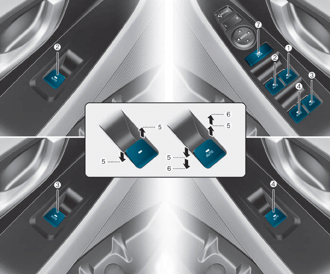
(1) Driver’s door power window
switch
(2) Front passenger’s door power
window switch
(3) Rear door (right) power window
switch
(4) Rear door (left) power window
switch
(5) Window opening and closing
(6) Automatic power window
(7) Power window lock switch

Copyright © 2025 www.hi30.net