Hyundai i-30: Crash Pad / Steering Column Shroud Panel
Components and components location

1. Steering column
shroud lower panel
|
2. Steering column
shroud upper panel
|
Repair procedures
[Steering column shroud upper panel]
| •
|
Put on gloves to prevent hand injuries.
|
|
| •
|
When removing with a flat-tip screwdriver or remover, wrap protective
tape around the tools to prevent damage to components.
|
| •
|
Use a plastic panel removal tool to remove interior trim pieces
without marring the surface.
|
| •
|
Take care not to bend or scratch the trim and panels.
|
|
|
1. |
Using a screwdriver or remover, remove the steering column shroud upper
panel (A).

|
|
2. |
Using a screwdriver or remover, remove the steering column shroud upper
panel (A).

|
|
3. |
To install, reverse removal procedure.
|
• |
Replace any damaged clips (or pin-type retainers).
|
|
|
[Steering column shroud lower panel]
| •
|
Put on gloves to prevent hand injuries.
|
|
| •
|
When removing with a flat-tip screwdriver or remover, wrap protective
tape around the tools to prevent damage to components.
|
| •
|
Use a plastic panel removal tool to remove interior trim pieces
without marring the surface.
|
| •
|
Take care not to bend or scratch the trim and panels.
|
|
|
1. |
Remove the crash pad lower panel.
(Refer to Crash Pad - "Crash Pad Lower Panel")
|
|
2. |
Remove the steering colume shroud upper panel.
(Refer to Crash Pad - "Steering Column Shroud Panel")
|
|
3. |
Loosen the mounting screws by turning the steering wheel to the left
and right, and remove the steering column shroud lower panel (A).

|
|
4. |
To install, reverse removal procedure.
|
• |
Replace any damaged clips (or pin-type retainers).
|
|
|
Components and components location
Component Location
1. Crash pad
lower panel
Repair procedures
Replacement
•
Put on gloves to prevent hand injuries...
Components and components location
Component Location
[LH]
1. Crash pad
side cover [LH]
[RH]
1...
Other information:
Components and components location
Component Location
1. Front door
outside handle
Repair procedures
Replacement
1.
Remove the plug hole (B).
2...
Cruise Control operation
1. CRUISE indicator
2. SET indicator
The Cruise Control system allows you
to drive at speeds above 20 mph (30
km/h) without depressing the accelerator
pedal.
WARNING
Take the following precautions:
Always set the vehicle speed
under the speed limit in your
country...
Categories
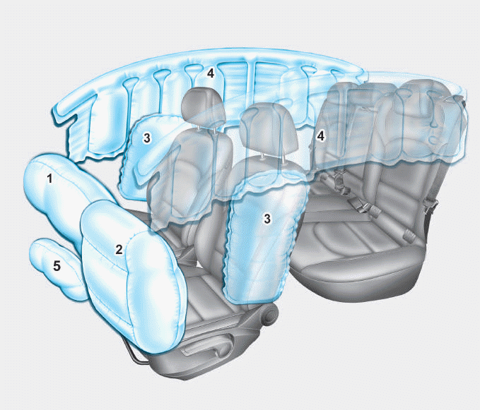
1. Driver’s front air bag
2. Passenger’s front air bag
3. Side air bag*
4. Curtain air bag*
5. Knee air bag*
6. Front passenger air bag ON/OFF
switch
read more


 Crash Pad Lower Panel
 Crash Pad Side Cover