Hyundai i-30: ABS (Anti-Lock Brake System) / Schematic diagrams
Hyundai i30 (PD) 2018-2025 Service Manual / Brake System / ABS (Anti-Lock Brake System) / Schematic diagrams
| Schematic Diagrams |
| [Without EPB] |


| [With EPB] |


| Termianal Function |
| [Without EPB] |

|
Pin No |
Description |
Current |
|
|
Max |
Min |
||
|
13 |
Ground for recirculation pump |
39 A |
10 A |
|
1 |
Voltage supply for pump motor |
39 A |
10 A |
|
25 |
Voltage supply for solenoid valves |
15 A |
2 A |
|
38 |
Ground for solenoid valves and ECU |
15 A |
2 A |
|
22 |
FL Wheel speed sensor signal |
16.8 mA |
5.9 mA |
|
33 |
RL Wheel speed sensor power |
16.8 mA |
5.9 mA |
|
19 |
RR Wheel speed sensor power |
16.8 mA |
5.9 mA |
|
18 |
FR Wheel speed sensor power |
16.8 mA |
5.9 mA |
|
6 |
FR Wheel speed sensor signal |
16.8 mA |
5.9 mA |
|
14 |
CAN LOW |
30 mA |
20 mA |
|
34 |
FL Wheel speed sensor power |
16.8 mA |
5.9 mA |
|
20 |
RL Wheel speed sensor signal |
16.8 mA |
5.9 mA |
|
32 |
Voltage for hybrid ECU |
1 A |
500 mA |
|
31 |
RR Wheel speed sensor signal |
16.8 mA |
5.9 mA |
|
30 |
Brake light switch |
10 mA |
5 mA |
|
26 |
CAN HIGH |
30 mA |
20 mA |
|
27 |
Wheel speed sensor output |
Open Draim |
|
|
4 |
ESS output |
20mA |
5mA |
|
23 |
Clutch switch (MT Only) |
10 mA |
5 mA |
|
10 |
Parking brake switch |
10 mA |
5 mA |
|
21 |
L-CAN LOW |
30 mA |
20 mA |
|
9 |
L-CAN HIGH |
30 mA |
20 mA |
| [With EPB] |

|
Pin No |
Desciption |
Current |
|
|
Max |
Min |
||
|
1 |
Voltage supply for pump motor |
39A |
10A |
|
2 |
RR EPB motor power |
30A |
- |
|
3 |
RR EPB motor ground |
30A |
- |
|
4 |
- |
- |
- |
|
5 |
Local CAN High |
30 mA |
20 mA |
|
6 |
Electric parking brake signal 1 |
20 mA |
- |
|
7 |
Electric parking brake signal 2 |
20 mA |
- |
|
8 |
Electric parking brake signal 3 |
20 mA |
- |
|
9 |
Electric parking brake signal 4 |
20 mA |
- |
|
10 |
- |
- |
- |
|
11 |
- |
- |
- |
|
12 |
RL EPB motor ground |
30A |
- |
|
13 |
RL EPB motor power |
30A |
- |
|
14 |
Ground for solenoid valves and ECU |
30A |
10A |
|
15 |
- |
- |
- |
|
16 |
- |
- |
- |
|
17 |
FR Wheel speed sensor signal |
16.8 mA |
5.9 mA |
|
18 |
- |
- |
- |
|
19 |
ESP OFF switch signal |
10 mA |
5 mA |
|
20 |
Local CAN Low |
30 mA |
20 mA |
|
21 |
Clutch stroke sensor signal |
- |
- |
|
22 |
- |
- |
- |
|
23 |
N' Signal |
200 mA |
100 mA |
|
24 |
- |
- |
- |
|
25 |
FR Wheel speed sensor power |
16.8 mA |
5.9 mA |
|
26 |
RR Wheel speed sensor power |
16.8 mA |
5.9 mA |
|
27 |
RL Wheel speed sensor signal |
16.8 mA |
5.9 mA |
|
28 |
- |
- |
- |
|
29 |
FL Wheel speed sensor signal |
16.8 mA |
5.9 mA |
|
30 |
Voltage supply for solenoid valves |
30A |
10A |
|
31 |
- |
- |
- |
|
32 |
Wheel speed sensor output |
Open drain |
- |
|
33 |
- |
- |
- |
|
34 |
Auto holding ON/OFF switch signal |
10 mA |
5 mA |
|
35 |
Brake light switch |
10 mA |
5 mA |
|
36 |
RR Wheel speed sensor signal |
16.8 mA |
5.9 mA |
|
37 |
IGN 1 |
5A |
1A |
|
38 |
RL Wheel speed sensor power |
16.8 mA |
5.9 mA |
|
39 |
FL Wheel speed sensor power |
16.8 mA |
5.9 mA |
|
40 |
- |
- |
- |
|
41 |
- |
- |
- |
|
42 |
- |
- |
- |
|
43 |
- |
- |
- |
|
44 |
C-CAN High |
30 mA |
20 mA |
|
45 |
C-CAN Low |
30 mA |
20 mA |
|
46 |
Voltage supply for pump motor |
40A |
10A |
 Description and operation
Description
This specification applies to HCU (Hydraulic Control Unit) and ECU (Electronic
Control Unit) of the HECU. (Hydraulic and Electronic Control Unit)
This specification is for the wiring design and installation of ABS ECU...
 Repair procedures
Inspection
ABS System Bleeding
This procedure should be followed to ensure adequate bleeding of air and filling
of the ESC unit, brake lines and master cylinder with brake fluid...
Other information:
Hyundai i30 (PD) 2018-2025 Service Manual: Idler
Repair procedures Removal and installation 1. Remove the drive belt. (Refer to Timing System - "Drive Belt") 2. Remove the idler (A). Tightening torque : 44...
Hyundai i30 (PD) 2018-2025 Service Manual: Turbo Charger & Exhaust Manifold
Components and components location Components 1. Catalytic converter (WCC) 2. Turbo manifold module 3. Catalytic converter (WCC) heat protector 4. Turbo charger gasket 5. Catalytic converter (WCC) gasket 6...
Categories
- Manuals Home
- 3rd Generation i30 Owners Manual
- 3rd Generation i30 Service Manual
- Engine compartment
- EPB malfunction indicator
- To activate the ISG system
- New on site
- Most important about car
Tailgate
Opening the tailgate
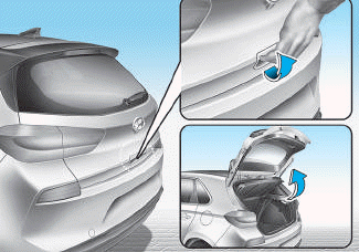
■ 5 Door, Wagon
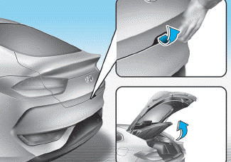
■ Fastback

Copyright © 2025 www.hi30.net