Hyundai i-30: ABS (Anti-Lock Brake System) / Description and operation
Hyundai i30 (PD) 2018-2025 Service Manual / Brake System / ABS (Anti-Lock Brake System) / Description and operation
| Description |
This specification applies to HCU (Hydraulic Control Unit) and ECU (Electronic
Control Unit) of the HECU. (Hydraulic and Electronic Control Unit)
This specification is for the wiring design and installation of ABS ECU.
This unit has the functions as follows.
| – |
Input of signal from the wheel speed sensors attached to each wheel.
|
| – |
Control of braking force.
|
| – |
Failsafe function.
|
| – |
Self diagnosis function.
|
| – |
Interface with the external diagnosis tester.
|
Installation Position : Engine Compartment
| – |
Brake tube length from Master cylinder port to HECU inlet port should
be max. 1m
|
| – |
The position should not be close to the engine block and not lower than
the wheel.
|
Operation
The ECU shall be put into operation by switching on the operating voltage (IGN).
On completion of the initialization phase, the ECU shall be ready for operation.
In the operating condition, the ECU shall be ready, within the specified limits
(voltage and temperature), to process the signals offered by the various sensors
and switches in accordance with the control algorithm defined by the software
and to control the hydraulic and electrical actuators.
Wheel Sensor Signal Processing
The ECU shall receive wheel speed signal from the four active wheel sensors.
The wheel signals are converted to voltage signal by the signal conditioning
circuit after receiving current signal from active wheel sensors and given as
input to the MCU.
Solenoid Valve Control
When one side of the valve coil is connected to the positive voltage that is
provided through the valve relay and the other side is connected to the ground
by the semiconductor circuit, the solenoid valve goes into operation.
The electrical function of the coils are always monitored by the valve test
pulse under normal operation conditions.
Voltage Limits
| – |
Overvoltage
When overvoltage is detected(above 16.8 V), the ECU switches off the
valve relay and shuts down the system.
When voltage is returned to operating range, the system goes back to
the normal condition after the initialization phase.
|
| – |
Undervoltage
In the event of undervoltage(below 9.3 V), ABS control shall be inhibited
and the warning lamp shall be turned on.
When voltage is returned to operating range, the warning lamp is switched
off and ECU returns to normal operating mode.
|
Pump Motor Checking
The ECU performs a pump motor test at a speed of 30km/h once after IGN is switched
on.
Diagnostic Interface
Failures detected by the ECU are encoded on the ECU, stored in a EEPROM and
read out by diagnostic equipment when the ignition switch is turned on.
The diagnosis interface can also be used for testing the ECU during production
of the ECU and for actuating the HCU (Air-bleeding line or Roll and Brake Test
line).
Warning Lamp Module
| [Super vision] |

| [General] |

| 1. |
ABS Warning Lamp
The active ABS warning lamp indicates the selftest and failure status
of the ABS. The ABS warning lamp shall be on :
|
| 2. |
EBD/Parking brake Warning Lamp
The active EBD warning lamp indicates the selftest and failure status
of the EBD. However, in case the Parking Brake Switch is turned on,
the EBD warning lamp is always turned on regardless of EBD functions.The
EBD warning lamp shall be on:
|
| ABS Control |
| 1. |
Normal Braking without ABS
|


| 2. |
Decrease Mode
|

| 3. |
Hold Mode
|

| 4. |
Increase Mode
|

 Components and components location
Components
[LHD]
1. ABS Control
Module (HECU)
2. Front Wheel Speed Sensor
3. Rear Wheel Speed Sensor
4...
 Schematic diagrams
Schematic Diagrams
[Without EPB]
[With EPB]
Termianal Function
[Without EPB]
Pin No
Description
Current
Max
Min
13
Ground for recirculation pump
39 A
10 A
1
Voltage supply for pump motor
39 A
10 A
25
Voltage supply for solenoid valves
15 A
2 A
38
Ground for solenoid valves and ECU
15 A
2 A
22
FL Wheel speed sensor signal
16...
Other information:
Hyundai i30 (PD) 2018-2025 Service Manual: Rear Combination Lamp
Repair procedures Removal 1. Disconnect the negative (-) battery terminal. 2. Remove the outside rear combination cover. 3. Remove the outside rear combination lamp assembly after loosening the bolts...
Hyundai i30 (PD) 2018-2025 Owner's Manual: Maintenance services
You should exercise the utmost care to prevent damage to your vehicle and injury to yourself whenever performing any maintenance or inspection procedures. We recommend you have your vehicle maintained and repaired by a HYUNDAI authorised repairer...
Categories
- Manuals Home
- 3rd Generation i30 Owners Manual
- 3rd Generation i30 Service Manual
- Shift-lock system. Shift-lock release
- FCA sensor
- Light bulbs
- New on site
- Most important about car
Gauges and meters
Speedometer
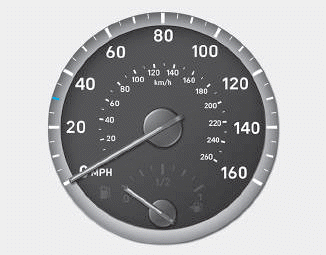
The speedometer indicates the speed of the vehicle and is calibrated in kilometers per hour (km/h) and/or miles per hour (MPH).
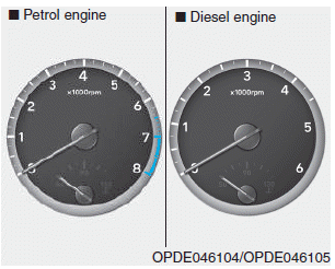
Tachometer
Copyright © 2025 www.hi30.net