Hyundai i-30: Ignition System / Schematic diagrams
Hyundai i30 (PD) 2018-2025 Service Manual / Engine Electrical System / Ignition System / Schematic diagrams
| Schematic Diagrams |


 Repair procedures
On-vehicle Inspection
Inspect ignition coil assembly and
Perform spark test
1.
Check for DTCs.
•
If a DTC is present, perform troubleshooting in accordance
with the procedure for that DTC...
Other information:
Hyundai i30 (PD) 2018-2025 Service Manual: Description and operation
Description Idle Stop & Go (ISG) system switches off the ignition when vehicle is stopped, and then restarts the ignition and starts the vehicle when accelerator is pushed. It temporarily stops the engine while waiting for signal or idling to improve fuel efficiency and reduce exhaust gas emission...
Hyundai i30 (PD) 2018-2025 Owner's Manual: Winter Precautions
Use high quality ethylene glycol coolant Your vehicle is delivered with high quality ethylene glycol coolant in the cooling system. It is the only type of coolant that should be used because it helps prevent corrosion in the cooling system, lubricates the water pump and prevents freezing...
Categories
- Manuals Home
- 3rd Generation i30 Owners Manual
- 3rd Generation i30 Service Manual
- Theft-alarm system
- Engine compartment
- Jump starting procedure
- New on site
- Most important about car
Gauges and meters
Speedometer
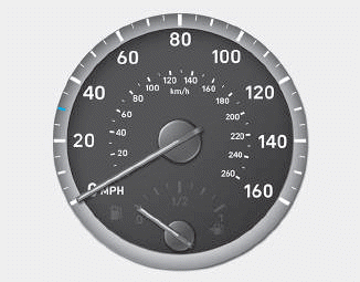
The speedometer indicates the speed of the vehicle and is calibrated in kilometers per hour (km/h) and/or miles per hour (MPH).
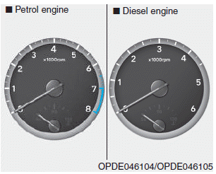
Tachometer

Copyright © 2025 www.hi30.net