Hyundai i-30: Brake System / Repair procedures
| Operation and Leakage Check |
Check all of the following items :
|
Component |
Procedure |
||||
|
Brake Booster (A) |
Check brake operation by applying the brakes during a test drive. If the
brakes do not work properly, check the brake booster. Replace the brake
booster as an assembly if it does not work properly or if there are signs
of leakage. |
||||
|
Piston cup and pressure cup inspection (B) |
|
||||
|
Brake hoses (C) |
Look for damage or signs of fluid leakage. Replace the brake hose with a
new one if it is damaged or leaking. |
||||
|
Caliper piston seal and piston boots (D) |
Check brake operation by applying the brakes. Look for damage or signs of fluid leakage. If the pedal does not work properly, the brakes drag, or there is damage or signs of fluid leakage, disassemble and inspect the brake caliper. Replace the boots and seals with new ones whenever the brake caliper is disassembled. |

Brake System Bleeding
|
| 1. |
Make sure the brake fluid in the reservoir is at the MAX (upper) level
line.
|
| 2. |
Have someone slowly pump the brake pedal several times, and then apply
pressure.
|
| 3. |
Loosen the right-rear brake bleed screw (A) to allow air to escape from
the system. Then tighten the bleed screw securely.
[Front]
[Rear]
|
| 4. |
Repeat the procedure for wheel in the sequence shown below until air
bubbles no longer appear in the fluid.
|
| 5. |
Refill the master cylinder reservoir to MAX (upper) level line.
|
Brake System (Judder Inspection)

 Brake System
..
 Brake Booster
Components and components location
Components
[LHD]
1. Reservoir
cap
2. Reservoir
3. Brake booster
4...
Other information:
Hyundai i30 (PD) 2018-2025 Service Manual: Stop Lamp Switch
Components and components location Components 1. Brake member assembly 2. Stop lamp switch 3. Return spring 4. Brake pedal arm assembly 5. Brake pedal pad Schematic diagrams Schematic Diagram System Circuit Diagram Terminal Function Teminal Description 1 IGN1 2 BS 3 - 4 B+ 5 Stop Lamp 6 Ground Troubleshooting Troubleshooting 1...
Hyundai i30 (PD) 2018-2025 Service Manual: Repair procedures
Removal 1. Remove the front bumper cover. (Refer to Body - "Front Bumper Cover") 2. Remove the horn (A) after disconnecting the connector (B) and loosening the mounting bolt...
Categories
- Manuals Home
- 3rd Generation i30 Owners Manual
- 3rd Generation i30 Service Manual
- LKA system operation
- Auto door lock/unlock features
- Light bulbs
- New on site
- Most important about car
Panorama sunroof
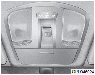
If your vehicle is equipped with a sunroof, you can slide or tilt your sunroof with the sunroof control lever located on the overhead console.

The ignition switch must be in the ON position before you can open or close the sunroof.
The sunroof can be operated for approximately 30 seconds after the ignition key is removed or turned to the ACC or LOCK(or OFF) position. However, if the front door is opened, the sunroof cannot be operated even within 30 seconds.
Copyright © 2025 www.hi30.net


