Hyundai i-30: Front Axle Assembly. Front Hub / Knuckle / Repair procedures
Hyundai i30 (PD) 2018-2025 Service Manual / Driveshaft and axle / Front Axle Assembly. Front Hub / Knuckle / Repair procedures
| Removal |
| 1. |
Loosen the wheel nuts slightly.
Raise the vehicle, and make sure it is securely supported.
|
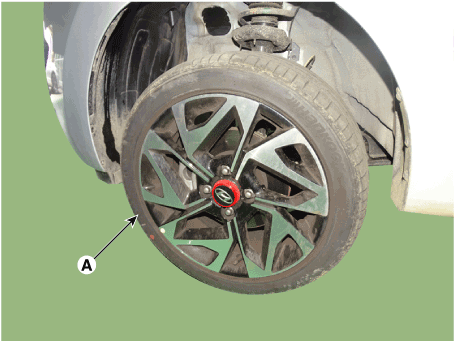
| 2. |
Remove the front wheel and tire (A) from the front hub.
|

| 3. |
Remove the front brake caliper.
(Refer to Brake System - "Front Disc Brake")
|
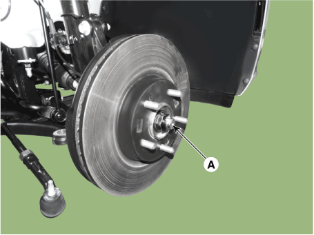
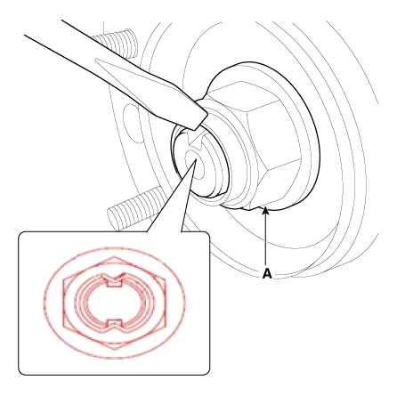
| 4. |
Loosen the driveshaft caulking nut (A).
|
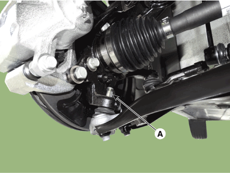
| 5. |
Remove the tie rod end ball joint.
|

| 6. |
Loosen the screw and then remove the front disc.
|
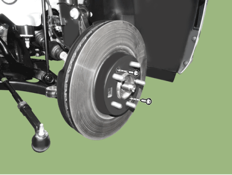
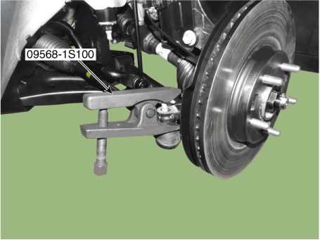
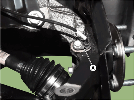
| 7. |
Loosen the lower arm nut (A) and then remove the lower arm ball joint
by using SST (09568-1S100).
|

| 8. |
Remove the driveshaft (A) from the front axle assembly (B).
|
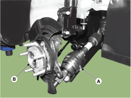
| 9. |
Loosen the bolt and then remove the wheel speed sensor (A).
|
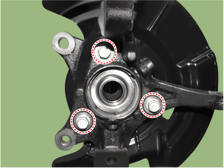
| 10. |
Remove the hub bearing from the front knuckle.
|
| 11. |
Loosen the mounting bolts and then remova the dust cover.
|
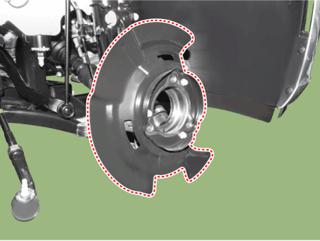
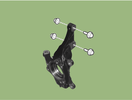
| 12. |
Loosen the strut mounting bolts, nuts and then remove the knuckle assembly.
|
| 13. |
To install, reverse the removal procedure
|
| 14. |
Check the alignment.
(Refer to Suspension System - "Alingment")
|
| Inspection |
| 1. |
Check the hub for cracks and the splines for wear.
|
| 2. |
Check the brake disc for scoring and damage.
|
| 3. |
Check the knuckle for cracks.
|
| 4. |
Check the bearing for cracks or damage.
|


Other information:
Hyundai i30 (PD) 2018-2025 Owner's Manual: ESC OFF usage
When Driving The ESC OFF mode should only be used briefly to help free the vehicle if stuck in snow or mud, by temporarily stopping operation of the ESC, to maintain wheel torque. To turn ESC off whilst driving, press the ESC OFF button whilst driving on a flat road surface...
Hyundai i30 (PD) 2018-2025 Service Manual: Description and operation
Description • Components location : DCT (Dual Clutch Transmission) • Function The dual clutch is installed within the transmission. The dual clutch comprises an odd clutch and an even clutch...
Categories
- Manuals Home
- 3rd Generation i30 Owners Manual
- 3rd Generation i30 Service Manual
- Front windscreen wiper service position
- Battery replacement
- Theft-alarm system
- New on site
- Most important about car
Air bag - supplemental restraint system
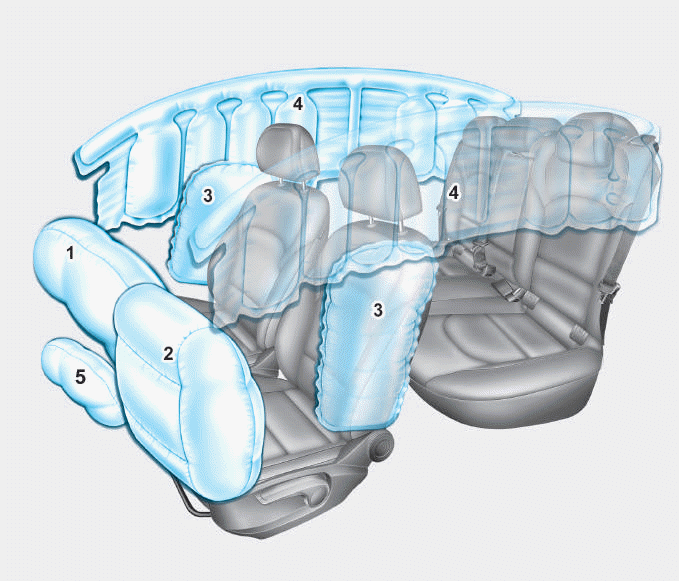
1. Driver’s front air bag
2. Passenger’s front air bag
3. Side air bag*
4. Curtain air bag*
5. Knee air bag*
6. Front passenger air bag ON/OFF
switch

Copyright © 2025 www.hi30.net