Hyundai i-30: Ignition Switch Assembly / Repair procedures
Hyundai i30 (PD) 2018-2025 Service Manual / Body Electrical System / Ignition Switch Assembly / Repair procedures
| Inspection |
| 1. |
Disconnect the key warning switch connector (A) and ignition switch
connector (B) from the steering column.
|
| 2. |
Check for continuity between the terminals.
|
| 3. |
If continuity is not specified, replace the switch.
|
| Removal |
| 1. |
Disconnect the negative (-) battery terminal.
|
| 2. |
Remove the driver crash pad lower panel.
(Refer to Body - "Crash Pad Lower Panel")
|
| 3. |
Remove the steering column upper and lower shroud panel.
(Refer to Body - "Steering Column Shroud Panel")
|
| 4. |
Remove the multifunction switch.
(Refer to Body Electrical System - "Multifunction Switch")
|
| 5. |
Remove the key warning / immobilizer connector.
|
| 6. |
Insert key and turn it to ACC position.
|
| 7. |
Pushing lock pin (B) with the awl.
|
| 8. |
Remove the key lock cylinder (A).
B : Key warning switch
C : Ignition switch connector
|
| 9. |
Disconnect the ignition switch connector (A).
|
| 10. |
Remove the ignition switch (B) after loosening the mounting bolts.
|
| Installation |
|
| 1. |
Install the key warning switch.
|
| 2. |
Connect the ignition switch connector after install the ignition switch.
|
| 3. |
Install the steering culumn shrouds panel.
|
| 4. |
Install the driver carsh pad lower panel.
|
| 5. |
Connect the negative (-) battery terminal
|
Other information:
Hyundai i30 (PD) 2018-2025 Service Manual: Release residual pressure in fuel line
Release Residual Pressure in Fuel Line • There may be some residual pressure even after "Release residual pressure in fuel line" work, so cover the hose connection with a shop towel to prevent residual fuel from spilling out before disconnecting any fuel connection...
Hyundai i30 (PD) 2018-2025 Service Manual: ESP OFF Switch
Description and operation Description 1. The ESP OFF switch is for the user to turn off the ESP system. 2. The ESP OFF lamp is on when ESP OFF switch is engaged. Repair procedures Removal 1...
Categories
- Manuals Home
- 3rd Generation i30 Owners Manual
- 3rd Generation i30 Service Manual
- Trip computer
- Engine coolant
- EPB malfunction indicator
- New on site
- Most important about car
Warning light and message

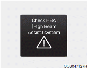
When the High Beam Assist (HBA)
System is not working properly, the
warning message will come on for a
few second. After the message disappears,
the master warning light ( )
will illuminate.
Copyright © 2025 www.hi30.net


