Hyundai i-30: Motor Driven Power Steering / MDPS Control Unit
Repair procedures
| •
|
If a DTC occurs in the ECU, check the connectors and wiring.
If no problem is found, replace the ECU.
|
|
| •
|
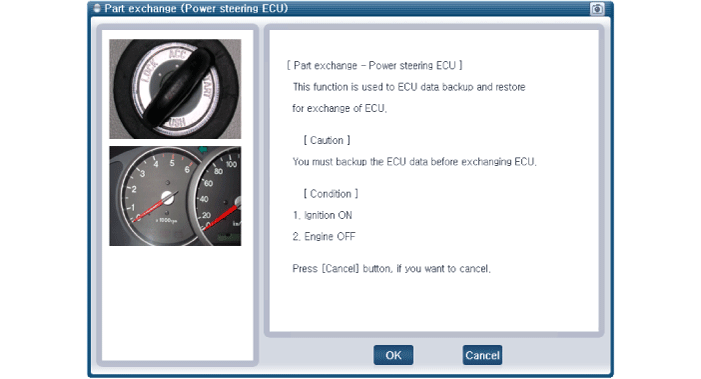
Before replacing the MDPS ECU, use the diagnostic device to
read the settings of the old ECU
|
|
|
1. |
Perform the "ECU data backup" by GDS following in the order below.
|
(1) |
Connect self - diagnosis connector (16pins) located in the lower
of driver side crash pad to self - diagnosis device.
|
|
(2) |
Turn the self - diagnosis device after key is ON.
|
|
(3) |
After Selecting the "vehicle model" and "EPS system" on GDS
vehicle selection screen.
|
|
(4) |
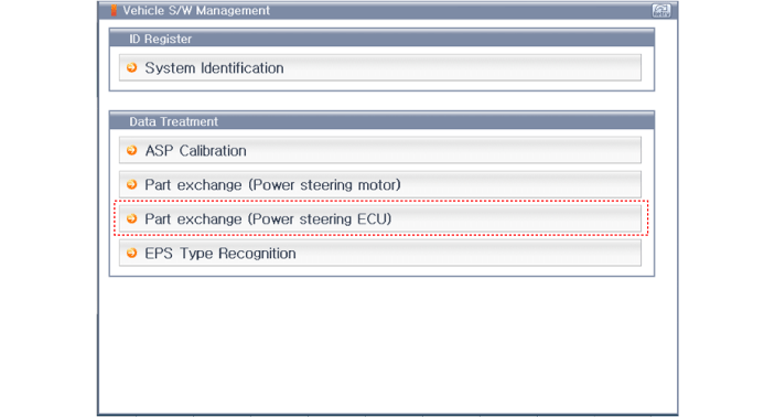
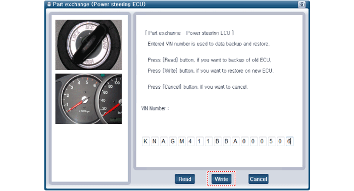
Select the "Part exchange(Power steering ECU)"
|
|
(5) |
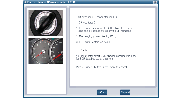
Follow the instructions shown on the screen.
|
|
(6) |
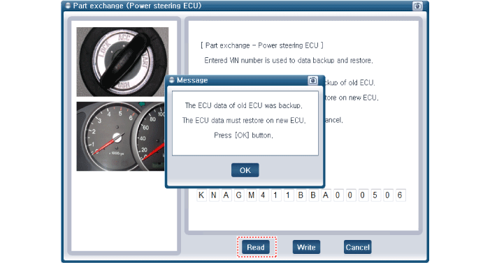
Insert the VIN number and then select the "Read" in order to
the ECU information save.
|
|
|
2. |
Disconnect the battery negative cable from the battery and then wait
for at least 30 seconds.
|
|
3. |
Remove the crash pad lower panel.
(Refer to Body - "Crash Pad Lower Panel")
|
|
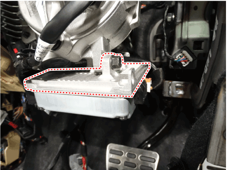
4. |
Disconnect the conector and loosening the than mounting bolts.
|
|
5. |
Install in the reverse order of removal.
|
|
6. |
Perform the "ECU data restore" by GDS following in the order below.
|
(1) |
Connect self - diagnosis connector (16pins) located in the lower
of driver side crash pad to self - diagnosis device.
|
|
(2) |
Turn the self - diagnosis device after key is ON.
|
|
(3) |
After Selecting the "vehicle model" and "EPS system" on GDS
vehicle selection screen.
|
|
(4) |
Select the "Part exchange(Power steering ECU)"
|
|
(5) |
Follow the instructions shown on the screen.
|
|
(6) |
Insert the VIN number and then select the "Write" in order to
the ECU information save.
|
|
|
7. |
Conduct the "ASP Calibration" by GDS.
(Refer to MDPS Control Unit- "Diagnosis with GDS")
|
|
9. |
Turn off the IGN switch and wait for 10 seconds or more. Then check
the operation after starting the engine.
|
| – |
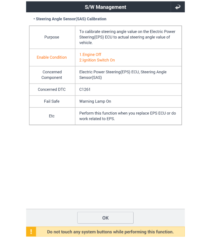
Steering-angle sensor detects the steering angle and steering angle
speed. Steering angle and steering angle speed are used for steering
wheel damping and return controls in addition to providing assistance
torque.
|
| •
|
You can use a scan tool to (GDS) check if the battery voltage
is proper before perform the "ASP Calibration".
|
| •
|
Make sure that no connector engaged to the vehicle or scan tool
is disconnected during the "ASP Calibration".
|
| •
|
Once the "ASP Calibration" is complete, turn off the IG switch
and wait for 10 seconds or more before starting the engine to
check the operation.
|
|
SAS Calibration procedures
|
1. |
Connect self - diagnosis connector (16pins) located in the lower of
driver side crash pad to self - diagnosis device.
|
|
2. |
Turn the self - diagnosis device after key is ON.
|
|
3. |
Turn the steering wheel to straight ahead position.
|
|
4. |
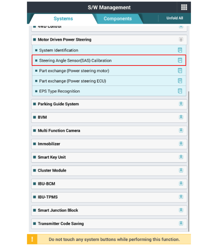
After Selecting the "vehicle model" and "system", select the "SAS Calibration"
on diagnostic tool vehicle selection screen.
|
|
6. |
Turn off the IG switch and wait for 10 seconds or more before starting
the engine. And then make sure that MDPS works properly.
|
Repair procedures
Replacement
1.
Disconnect the battery negative cable from the battery and then wait
for at least 30 seconds...
Repair procedures
Removal
1.
Remove the MDPS assembly.
(Refer to Steering System - "MDPS Assembly")
2...
Other information:
Ventilation
1. Set the mode to the
position.
2. Set the air intake control to the
outside (fresh) air position.
3. Set the temperature control to the
desired position.
4. Set the fan speed control to the
desired speed.
Heating
1. Set the mode to the
position...
Components and components location
Component Location
1. Heater unit
assembly
Components
1. Heater
core cover
2. Heater core & seal assembly
3. Mode control actuator
4...
Categories
Speedometer
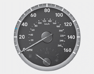
The speedometer indicates the
speed of the vehicle and is calibrated
in kilometers per hour (km/h) and/or
miles per hour (MPH).
Tachometer
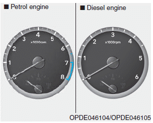
read more


 MDPS Motor
 MDPS Column and Housing