Hyundai i-30: Convenient features of your vehicle / Lighting
 Trip computer
The trip computer is a microcomputer-
controlled driver information system
that displays information related
to driving.
Information
Some driving information stored in the
trip computer (for example Average
Vehicle Speed) resets if the battery is
disconnected...
 Exterior lights
Lighting control
To operate the lights, turn the knob at
the end of the control lever to one of
the following positions:
(1) O (OFF) position
(2) AUTO light position (if equipped)
(3) Position lamp position
(4) Headlamp position
AUTO light position
When the light switch is in the AUTO
position, the position lamp and headlamp
will be turned ON or OFF automatically
depending on the amount
of light outside the vehicle...
Other information:
Hyundai i30 (PD) 2018-2025 Service Manual: Water Jacket Seperator
Repair procedures Removal and Installation 1. Remove the cylinder head assembly. (Refer to Cylinder Head Assembly - "Cylinder Head") 2. Remove the water jacket separator (A)...
Hyundai i30 (PD) 2018-2025 Owner's Manual: Smart cruise control (SCC) with stop & go system
➀ Cruise indicator ➁ Set speed ➂ Vehicle-to-vehicle distance To see the SCC screen on the LCD display in the cluster, select ASSIST mode (). For more information, refer to “LCD Display Modes” in chapter 3. The Smart Cruise Control System allows you to program the vehicle to maintain constant speed and minimum distance between the vehicle ahead...
Categories
- Manuals Home
- 3rd Generation i30 Owners Manual
- 3rd Generation i30 Service Manual
- Cruise control
- Trip computer
- Brake/clutch fluid
- New on site
- Most important about car
Bonnet
Opening the bonnet

1. Park the vehicle and set the parking brake.
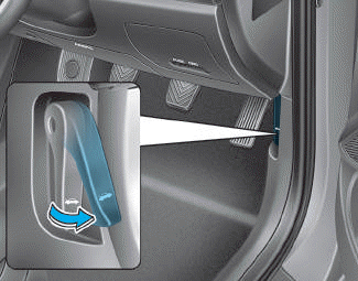
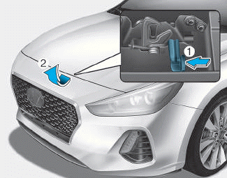
2. Pull the release lever to unlatch the bonnet. The bonnet should pop open slightly.

Copyright © 2025 www.hi30.net
