Hyundai i-30: Front Seat / Front Seat Frame Assembly
Hyundai i30 (PD) 2018-2025 Service Manual / Body (Interior and Exterior) / Front Seat / Front Seat Frame Assembly
Components and components location
| Component Location |

| 1. Front seat
back frame assembly |
2. Front seat
cushion frame assembly |
Repair procedures
| Replacement |
|

|

| 1. |
Remove the front seat back cover.
(Refer to Front Seat - "Front Seat Back Cover")
|
| 2. |
Remove the front seat cushion cover.
(Refer to Front Seat - "Front Seat Cushion Cover")
|
| 3. |
Remove the SAB module.
(Refer to Restraint - "Side Airbag (SAB) Module")
|
| 4. |
Remove the lumber support assembly.
(Refer to Body Electrical System - "Lumber Support Unit")
|
| 5. |
Disconnect the connectors (C).
|
| 6. |
After loosening the mounting bolts, detach the front seat back frame
assembly (A) from the front seat cushion frame assembly (B).
|

| 7. |
To install, reverse removal procedure.
|

 Front Seat Cushion Cover
Components and components location
Component Location
1. Front seat
cushion cover
Repair procedures
Replacement
•
Put on gloves to prevent hand injuries...
 Rear Seat
..
Other information:
Hyundai i30 (PD) 2018-2025 Service Manual: Rear Transverse Trim
Components and components location Component Location 1. Rear transverse trim Repair procedures Replacement • Put on gloves to prevent hand injuries...
Hyundai i30 (PD) 2018-2025 Service Manual: Smart Key Unit
Components and components location Components No Connector A Connector B Connector C 1 - IGN 2 Relay output Battery signal 2 SSB Switch 1 input C CAN (Low) - 3 Driver door antenna switch input C CAN (High) Immoblizer antenna power 4 - B CAN (High) Driver out side handle antenna power 5 - B CAN (Low) Assist out side handle antenna power 6 - SSB Illumination (orange) Bumper antenna power 7 RPM Input - Interior antenna 1 power 8 Start signal feedback input SSB Illumination (+) output Interior antenna 2 power 9 clutch switch input ESCL enable output Interior antenna 3 power 10 - Battery power - 11 Starter relay output IGN 1 Relay output - 12 Power 1 ESCL COM - 13 SSB Switch 2 input EMS COM ESCL (-) output 14 Assist door antenna switch input - Immoblizer antenna ground 15 - SSB Illumination (-) output Driver out side handle antenna ground 16 Clutch switch input SSB LED Output Assist out side handle antenna ground 17 ESCL unlock swtich input SSB LED IGN Output Bumper antenna ground 18 Wheel speed sensor input External buzzer Interior antenna 1 ground 19 ACC Input - Interior antenna 2 ground 20 IGN 1 ESCL (+) output Interior antenna 3 ground 21 Brake switch input - 22 ACC Relay input GND Power 2 Schematic diagrams Circuit Diagram Repair procedures Removal Smart Key Unit 1...
Categories
- Manuals Home
- 3rd Generation i30 Owners Manual
- 3rd Generation i30 Service Manual
- To activate the ISG system
- Battery replacement
- Cruise control
- New on site
- Most important about car
Gauges and meters
Speedometer
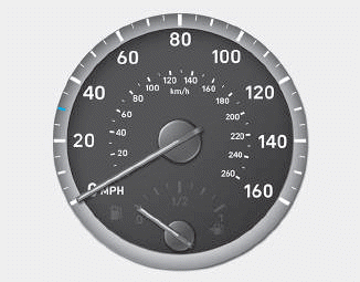
The speedometer indicates the speed of the vehicle and is calibrated in kilometers per hour (km/h) and/or miles per hour (MPH).
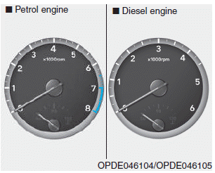
Tachometer

Copyright © 2025 www.hi30.net