Hyundai i-30: ESP (Electronic Stability Program) System / Description and operation
Hyundai i30 (PD) 2018-2025 Service Manual / Brake System / ESP (Electronic Stability Program) System / Description and operation
| Description of ESP |
Optimum driving safety now has a name : ESP, the Electronic Stability Program.
ESP recognizes critical driving conditions, such as panic reactions in dangerous
situations, and stabilizes the vehicle by wheel-individual braking and engine
control intervention with no needfor actuating the brake or the gas pedal.
ESP adds a further function known as Active Yaw Control (AYC) to the ABS, TCS,
EBD and ESP functions. Whereas the ABS/TCS function controls wheel slip during
braking and acceleration and, thus, mainly intervenes in the longitudinal dynamics
of the vehicle, active yaw control stabilizes the vehicle about its vertical
axis.
This is achieved by wheel individual brake intervention and adaptation of the
momentary engine torque with no need for any action to be taken by the driver.
ESP essentially consists of three assemblies : the sensors, the electronic control
unit and the actuators.
Of course, the stability control feature works under all driving and operating
conditions. Under certain driving conditions, the ABS/TCS function can be activated
simultaneously with the ESP function in response to a command by the driver.
In the event of a failure of the stability control function, the basic safety
function, ABS, is still maintained.
Description of ESP Control
ESP system includes ABS/EBD, TCS and AYC (Active yaw control) function.
ABS/EBD function : The ECU changes the active sensor signal (current shift)
coming from the four wheel sensors to the square waveform.By using the input
of above signals, the ECU calculates the vehicle speed and the acceleration
& deceleration of the four wheels.And, the ECU judges whether the ABS/EBD should
be actuated or not.
TCS function prevents the wheel slip of drive direction by adding the brake
pressure and engine torque reduction via CAN communication.TCS function uses
the wheel speed sensor signal to determine the wheel slip as far as ABS function.
AYC function prevents unstable maneuver of the vehicle. To determine the vehicle
maneuver, AYC function uses the maneuver sensor signals (Yaw Rate Sensor, Lateral
Acceleration Sensor, Steering Wheel Angle Sensor).
If vehicle maneuver is unstable (Over Steer or Under Steer), AYC function applies
the brake pressure on certain wheel, and send engine torque reduction signal
by CAN.
After the key-on, the ECU continually diagnoses the system failure. (self-diagnosis)If
the system failure is detected, the ECU informs driver of the system failure
through the BRAKE/ABS/ESP warning lamp. (fail-safe warning)
Input and Output Diagram
| ESP Operation Mode |
| 1. |
STEP 1
The ESP analyzes the intention of the driver.
|
| 2. |
STEP 2
It analyzes the movement of the ESP vehicle.
|

| 3. |
STEP 3
The HECU calculates the required strategy, then actuates the appropriate
valves and sents torque control requests via CAN to maintain vehicle
stability.
|
ESP Operation Mode
| 1. |
ESP Non-operation-Normal braking.
|

| 2. |
ESP Increase Mode
|
| 3. |
ESP Hold Mode (FR is only controlled.)
|
| 4. |
ESP Decrease Mode (FR is only controlled)
|
| [Super vision] |
| [General] |
ABS Warning Lamp
The active ABS warning lamp indicates the self-test and failure status of the
ABS. The ABS warning lamp shall be on:
| – |
During the initialization phase after IGN ON. (continuously 3 seconds).
|
| – |
In the event of inhibition of ABS functions by failure.
|
| – |
During diagnostic mode.
|
| – |
When the ECU Connector is separated from ECU.
|
EBD/Parking Brake Warning Lamp
The active EBD warning lamp indicates the self-test and failure status of the
EBD. However, in case the Parking Brake Switch is turned on, the EBD warning
lamp is always turned on regardless of EBD functions. The EBD warning lamp shall
be on:
| – |
During the initialization phase after IGN ON. (continuously 3 seconds).
|
| – |
When the Parking Brake Switch is ON or brake fluid level is low.
|
| – |
When the EBD function is out of order .
|
| – |
During diagnostic mode.
|
| – |
When the ECU Connector is separated from ECU.
|
ESP Function/Warning Lamp (ESP System)
The ESP Function/Warning lamp indicates the self-test and failure status of
the ESP.
The ESP Function/Warning lamp operates under the following conditions :
| – |
During the initialization phase after IGN ON. (continuously 3 seconds).
|
| – |
In the event of inhibition of ESP functions by failure.
|
| – |
During dignostic mode.
|
| – |
When the ESP control is operating. (Blinking - 2Hz)
|
ESP OFF Lamp (ESP System)
The ESP OFF lamp indicates the self-test and operating status of the ESP.
The ESP OFF lamp is turned on under the following conditions :
| – |
During the initialization phase after IGN ON. (continuously 3 seconds).
|
| – |
When driver turn off the ESP function by on/off switch.
|
ESP ON/OFF Switch (ESP System)
The ESP On/Off Switch shall be used to toggle the ESP function between On/Off
states based upon driver input.
The On/Off switch shall be a normally open, momentary contact switch.
Initial status of the ESP function is on and the switch is used to request an
ESP status change.
 Components and components location
Components
[LHD]
1. ESP Control
Module (HECU)
2. Front Wheel Speed Sensor
3. Rear Wheel Speed Sensor
4...
 Schematic diagrams
Schematic Diagrams
[Without EPB]
[With EPB]
Terminal Function
[EPB None Apply]
PIN No
Desciption
Current
max
min
1
Voltage supply for pump motor
40A
10 MΩ
2
-
1...
Other information:
Hyundai i30 (PD) 2018-2025 Service Manual: Camshaft Position Sensor (CMPS)
Description and operation Description Camshaft Position Sensor (CMPS) is a hall sensor and detects the camshaft position by using a hall element. It is related with Crankshaft Position Sensor (CKPS) and detects the piston position of each cylinder which the CKPS can't detect...
Hyundai i30 (PD) 2018-2025 Service Manual: Filler-Neck Assembly
Repair procedures Removal 1. Open the fuel filler door and remove the filler-neck assembly mounting bolts (A). 2. Remove LH rear wheel guard. (Refer to Body (Interior and Exterior) - "Rear Wheel Guard") 3...
Categories
- Manuals Home
- 3rd Generation i30 Owners Manual
- 3rd Generation i30 Service Manual
- Jump starting procedure
- Cruise control
- Shift-lock system. Shift-lock release
- New on site
- Most important about car
Turn signals and lane change signals
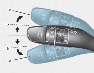
To signal a turn, push down on the lever for a left turn or up for a right turn in position (A). To signal a lane change, move the turn signal lever slightly and hold it in position (B).The lever will return to the OFF position when released or when the turn is completed.

Copyright © 2025 www.hi30.net