Hyundai i-30: Tire Pressure Monitoring System / Description and operation
TREAD Lamp
| – |
Tire Under Inflation / Leak Warning.

|
|
1. |
Turn on condition
| –
|
When tire pressure is below allowed threshold
|
| –
|
When rapid leak is detected by the sensor.
|
| –
|
Indicates that tire needs to be re-inflated to placard pressure
/ repaired.
|
|
|
2. |
Turn off condition
| –
|
Under-inflation ; When tire pressure is above (warning threshold
+ hysteresis).
|
| –
|
Rapid Leak ; When tire pressure is above (leak warning threshold).
|
|
DTC Warning
|
1. |
Turn on condition
| –
|
When the system detects a fault that is external to the receiver/
sensor.
|
| –
|
When the system detects a receiver fault.
|
| –
|
When the system detects a sensor fault.
|
|
|
2. |
Turn off condition
| –
|
If the fault is considered as 'critical', then the lamp is held
on throughout the current Ignition cycle (even if the DTC has
been demoted). This is because it is important to bring the
problem to the drivers attention. On the following Ignition
cycle, the demotion conditions will be re-checked. If the demotion
conditions occur, the lamp will be turned off. It will be held
on until DTC demotion checking is completed.
|
| –
|
'Non critical' faults are those that can occur temporarily e.g.
vehicle battery under voltage. The lamp is therefore turned
off when the DTC demotion condition occurs.
|
|
If the vehicle starts within 19 minutes after the replacement
of the wheel of the stopped vehicle, the TPMS Malfunction Indicator
on the instrument cluster illuminates.
|
– |
The above symptom is due to communication failure between
the BCM and the replaced TPMS ID.
|
|
– |
This communication failure indicator turns off in 19
minutes after the vehicle stops through the BCM’s automatic
learning process of TPMS ID.
(When driving the vehicle after stopping for over 19
minutes, the indicator turns off automatically.)
|
|
|
System Fault
|
1. |
General Function
| –
|
The system monitors a number of inputs across time in order
to determine that a fault exists.
|
| –
|
Faults are prioritized according to which has the most likely
cause.
|
| –
|
Maximum fault store is equal to 15.
|
| –
|
Certain faults are not covered through DTC. The main ones are
:
|
|
a. |
Sensor thermal shutdown (over 257 °F/ 125 °C).
|
|
b. |
Ignition Line stuck ; requires observation of lamps
at Ignition ON to diagnose.
|
|
|
Components
1. Body control
module (BCM)
2. TPMS sensor (FL)
3. TPMS sensor (RL)
4. TPMS sensor
(FR)
5...
Description and operation
Description
1.
General description
WU is a sensor placed in the tire that reports pressure and temperature...
Other information:
Specification
Item
Specification
Power source
3V
Operating temperature
-30°C to +75°C (-22°F to +167°F)
RF Modulation
FSK
LF Modulation
ASK
RF frequency
433...
Removal
[Manual Transaxle Type]
1.
Turn ignition switch OFF and disconnect the negative (-) battery cable.
2.
Remove the clutch pedal.
(Refer to Clutch System - "Cluch Pedal")
3...
Categories

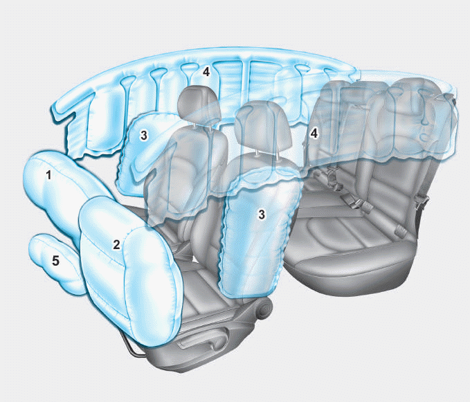
1. Driver’s front air bag
2. Passenger’s front air bag
3. Side air bag*
4. Curtain air bag*
5. Knee air bag*
6. Front passenger air bag ON/OFF
switch
read more
 Components and components location
 TPMS Sensor


