Hyundai i-30: Wireless Power Charger System / Troubleshooting
Wireless Power Charger System Troubleshooting
Trouble status
|
Inspection item
|
Inspection
|
Not charged
|
Check the mobile phone status
|
R-1
|
Amber LED blinks
|
Overcurrent
|
R-2
|
Overheating
|
R-2
|
Foreign matter
|
R-2
|
R-1. Check the wireless power charger system operation
|
1. |
If the placement of a mobile phone is not detected
|
(1) |
If the internal temperature of the mobile phone battery is high,
the mobile phone itself turns "OFF" the power.
|
The temperature at which the power is automatically
turned "OFF" differs by mobile phone model.
|
|
|
(2) |
If the mobile phone was placed outside the charging range
|
|
(3) |
If the mobile phone was placed by its LCD side on the charging
pad surface (if the phone was placed upside down)
|
|
(4) |
If the mobile phone was turned 180°
|
|
|
2. |
Check that the amber LED of the wireless charging lamp turns on when
the mobile phone is in normal condition and is correctly placed.
|
R-2. Check for overcurrent, overheating and foreign matter
|
1. |
Overcurrent : Charging stops in overcurrent of over 4.5 A
|
(1) |
The overcurrent error status will be reset when the current
falls under 4.5 A or when ACC is turned off and on.
|
|
|
2. |
Overheating : The unit will be automatically turned "OFF" when the internal
temperature of the wireless charging unit is over 158°F (70°C).
|
(1) |
The error status will be reset when the internal temperature
of the wirelss charging unit falls under 149°F (65°C).
|
|
|
3. |
Foreign matter : When metallic objects such as coins, clips and precious
metals are detected, charging will be stopped to prevent overheating.
|
(1) |
Error status will be reset when foreign matter is removed.
|
|
• |
The amber LED of the charging display lamp blinks 10
times for 10 seconds, and then it is turned off for
50 seconds (total 60 seconds).
|
|
• |
The process is repeated for every 60 seconds.
|
|
• |
Turning ACC OFF/ON resets the error status and returns
to normal operation.
|
|
|
Description and Operation
Wireless Power Charger System
During ACC or IG ON, battery voltage is supplied to the wireless power charger
system to transmit an output of 5 W to mobile phone...
Components and positions
Components
Circuit diagram
Circuit Diagram
Repair procedures
Removal
Handling wireless charging system parts by wet hands may cause electric
shock...
Other information:
Your vehicle is equipped with a side air
bag in each front seat. The purpose of
the air bag is to provide the vehicle’s
driver and the front passenger with
additional protection than that offered
by the seat belt alone.
The side air bags are designed to
deploy during certain side impact collisions,
depending on the crash
severity, angle, speed and point of
impact...
This warning message is displayed
when vehicle is driven slowly on a
grade and the vehicle detects that
the brake pedal is not applied.
Steep grade
Driving up hills or on steep grades:
To hold the vehicle on an incline
use the foot brake or the parking
brake...
Categories

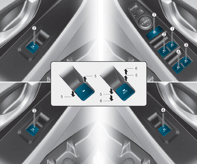
(1) Driver’s door power window
switch
(2) Front passenger’s door power
window switch
(3) Rear door (right) power window
switch
(4) Rear door (left) power window
switch
(5) Window opening and closing
(6) Automatic power window
(7) Power window lock switch
read more
 Description and operating principle
 Wireless Power Charging Unit

