Hyundai i-30: SRSCM / SRS Control Module (SRSCM)
Components and components location
1. SRSCM (Supplemental
Restraint System Control Module)
|
|
Description and operation
| • |
Supplemental Restraint System Control Module (SRSCM) determines whether
and when to deploy air bag module, seat belt pretensioner (BPT) and
emergency fastenig device (EFD).
|
| • |
It supplies the air bag module with the power required to deploy the
module or the BPT and EFD.
|
| • |
It also performs self-diagnosis function of the supplemental restraint
system.
|
Repair procedures
|
1. |
Remove the ignition key from the vehicle.
|
|
2. |
Disconnect the battery negative cable and wait for at least three minutes
before beginning work.
|
|
3. |
Remove the floor console.
(Refer to Body - "Floor Console Assembly")
|
|
4. |
Pull up the lock (A), of the SRSCM connector, then disconnect the connector.
|
|
5. |
Remove the SRSCM nuts from the SRSCM, then remove the SRSCM.
|
|
1. |
Remove the ignition key from the vehicle.
|
|
2. |
Disconnect the battery negative cable and wait for at least three minutes
before beginning work.
|
|
3. |
Install the SRSCM (A) with the SRSCM mounting nouts.
|
Tightening torque :
7.8 - 10.8 N.m (0.8 - 1.0 kgf.m, 5.8 - 7.2 lb-ft)
|
|
|
4. |
Connect the SRSCM harness connector.
|
|
5. |
Install the heater ducts and floor console.
(Refer to Body - "Floor Console Assembly")
|
|
6. |
Reconnect the battery negative cable.
|
|
7. |
After installing the SRSCM, confirm proper system operation :
| •
|
Turn the ignition switch ON; the SRS indicator light should
be turned on for about six seconds and then turns off.
|
|
After replacing the SRSCM with a new one, the "Variant Coding" procedure must
be performed.
| 1) |
On SRSCM variant coding mode, the airbag warning lamp periodically
blinks (ON : 0.5sec., OFF : 0.5sec.) until the coding is normally
completed.
|
| 2) |
If the variant coding fails, DTC B1762 (ACU Coding Error) will
be displayed and the warning lamp will turn on.
In this case, perform the variant coding procedure again after
confirming the cause in "DTC Fault State Information".
Variant Coding can be performed up to 255 times, but if the
number of coding work exceeds 255 times, DTC B1683 (Exceed Maximum
coding Number) will be displayed and SRSCM must be replaced.
|
| 3) |
If the battery voltage is low (less than 9V), DTC B1102 will
be displayed. In this case, charge the battery before anything
else, and then perform the variant coding procedure.
DTC B1762 (ACU Coding Error) and B1102 (Battery Voltage Low)
may be displayed simultaneously.
|
|
Variant Coding Procedure
|
1. |
Turn the ignition switch OFF.
|
|
3. |
Turn the ignition switch ON without the engine running.
|
|
4. |
Select vehicle name and airbag system.
|
|
5. |
Select variant coding mode.
|
|
6. |
Follow the steps on the screen below.
|
(1) |
Initial ACU Variant Coding screen
|
|
(2) |
VIN Code entering screen
|
|
(3) |
Variant Coding's proceeding screen-1
|
|
(4) |
Variant Coding's proceeding screen-2
|
|
(5) |
Variant Coding is completed
|
|
| 1) |
This screen is shown when you try variant coding on the SRSCM
which has been performed before.
|
| 2) |
This screen is shown when communication failure has occurred.
|
|
■ Off-Line Type on GDS (Use when not connected to the internet)
|
1. |
Turn the ignition switch OFF.
|
|
3. |
Turn the ignition switch ON without the engine running.
|
|
4. |
Select vehicle name and airbag system.
|
|
5. |
Select variant coding mode.
|
|
6. |
Follow the steps on the screen below.
|
(1) |
Initial ACU Variant Coding screen
|
|
(2) |
ACU Coding Code entering screen
|
|
(3) |
Rechecking ACU Coding Code entering screen
|
|
(4) |
Variant Coding's proceeding screen-1
|
|
(5) |
Variant Coding's proceeding screen-2
|
|
(6) |
Variant Coding is completed
|
1) |
This screen is shown when you try variant coding
on the SRSCM which has been performed before.
|
|
|
|
Components and components location
Components
1. Front Impact
Sensor (FIS)
Description and operation
Description
•
The front impact sensors (FIS) are installed on the upper of the side
panel in Front End Module (FEM)...
Other information:
Variant Coding
When you need variant coding:
–
Replace Front View Camera with a new one
※ EOL Variant Coding and calibration required for new replacement
Front View Camera Variant Coding
Front view camera variant coding makes it possible to operate functions for
each vehicle type...
Ventilation
1. Set the mode to the position.
2. Set the air intake control to the
outside (fresh) air position.
3. Set the temperature control to the
desired position.
4. Set the fan speed control to the
desired speed.
Heating
1. Set the mode to the position...
Categories
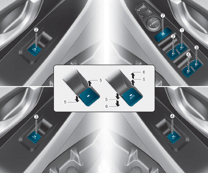
(1) Driver’s door power window
switch
(2) Front passenger’s door power
window switch
(3) Rear door (right) power window
switch
(4) Rear door (left) power window
switch
(5) Window opening and closing
(6) Automatic power window
(7) Power window lock switch
read more

 SRSCM
SRSCM Front Impact Sensor (FIS)