Hyundai i-30: Front View Camera System / Front View Camera Unit
Hyundai i30 (PD) 2018-2025 Service Manual / Advanced Driver Assistance System (ADAS) / Front View Camera System / Front View Camera Unit
Schematic diagrams
| Circuit Diagram |
Repair procedures
| Removal |
| 1. |
Disconnect the negative (-) battery terminal.
|
| 2. |
Remove the front view camera cover (A) and (B).
|
| 3. |
Disconnect the front view camera connector (A).
|
| 4. |
Remove the front view camera unit (A) by releasing the coupler (B).
|

| Installation |
| 1. |
Install in the reverse order of removal.
|
| 2. |
When if replacing the front view camera with a new one, perform the
"Variant Coding" procedure by using the Diagnostic Tools.
|
| 3. |
Perform the front view camera unit calibration.
(Refer to Repair procedures - "Service Point Target Auto Calibration
(SPTAC)")
|
 Repair procedures
Variant Coding
When you need variant coding:
–
Replace Front View Camera with a new one
※ EOL Variant Coding and calibration required for new replacement
Front View Camera Variant Coding
Front view camera variant coding makes it possible to operate functions for
each vehicle type...

Other information:
Hyundai i30 (PD) 2018-2025 Service Manual: Antenna
Components and components location Components [AM/FM Antenna] Repair procedures Removal Roof Antenna 1. Disconnect the negative (-) battery terminal. 2. Remove the roof trim assembly...
Hyundai i30 (PD) 2018-2025 Owner's Manual: Air bag - supplemental restraint system
1. Driver’s front air bag 2. Passenger’s front air bag 3. Side air bag* 4. Curtain air bag* 5. Knee air bag* 6. Front passenger air bag ON/OFF switch The vehicles are equipped with a Supplemental Air Bag System for the driver’s seat and front passenger’s seats...
Categories
- Manuals Home
- 3rd Generation i30 Owners Manual
- 3rd Generation i30 Service Manual
- Shift-lock system. Shift-lock release
- Auto door lock/unlock features
- Drive mode integrated control system
- New on site
- Most important about car
Bonnet
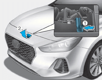
Opening the bonnet
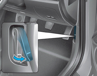
1. Park the vehicle and set the parking brake.
2. Pull the release lever to unlatch the bonnet. The bonnet should pop open slightly.

Copyright © 2025 www.hi30.net