Hyundai i-30: Dual Clutch System / Dual Clutch Assembly
Hyundai i30 (PD) 2018-2025 Service Manual / DCT(Dual Clutch Transmission) System / Dual Clutch System / Dual Clutch Assembly
Components and components location
| Components |

| 1. Dual clutch
assembly 2. Snap ring |
3. Spline hub 4. Retaining ring |
Repair procedures
| Removal |
| 1. |
Remove the dual clutch transmission from the vehicle.
(Refer to Dual Clutch System - "Repair procedures")
|
| 2. |
Remove the retaining (A) and then removing the spline hub (B).
|

| 3. |
Remove the snap ring (A).
|

| 4. |
Remove the dual clutch assembly (A) by using the special service tool
[SST No.: 09430-C1180].
|

| Installation |
|


| 1. |
Install the SST (No.:09430-2A240) on the support bearing within the
dual clutch assembly (A).
|

| 2. |
Install the SST (No. : 09430-2A240) on the clutch housing side.
|
| 3. |
Install the dual clutch assembly (A) using the SST (No. : 09430-2A240).
|

| 4. |
Install the snap ring (A).
|
| 5. |
Install the spline hub (B) and the install the snap ring (A).
|
| 6. |
Perform the work procedures for abrasion compensation reset after installing
the new dual clutch assembly.
(Refer to Clutch Actuator Assembly - "Adjustment")
|
| 7. |
Perform the clutch touch point learning procedure using the diagnostic
tool after replacing the dual clutch assembly.
|

 Description and operation
Description
•
Components location : DCT (Dual Clutch Transmission)
•
Function
The dual clutch is installed within the transmission...
 Clutch Engagement Fork and Engagement Bearing
Components and components location
Components
1. Engagement bearing sleeve
2. Clutch engagement fork
3. Engagement bearing 1 (Odd)
4...
Other information:
Hyundai i30 (PD) 2018-2025 Service Manual: Troubleshooting
Troubleshooting Symptom Possible cause Remedy Hard steering Improper front wheel alignment Excessive turning resistance of lower arm ball joint Low tire pressure No power assist Correct Replace Adjust Repair and replace Poor return of steering wheel to center Improper front wheel alignment Correct Poor or rough ride Improper front wheel alignment Malfunctioning shock absorber Broken or worn stabilizer Broken or worn coil spring Worn lower arm bushing Correct Repair or replace Replace Replace Replace the lower arm assembly Abnormal tire wear Improper front wheel alignment Improper tire pressure Malfunctioning shock absorber Correct Adjust or replace Replace Wandering Improper front wheel alignment Poor turning resistance of lower arm ball joint Loose or worn lower arm bushing Correct Repair Retighten or replace Vehicle pulls to one side Improper front wheel alignment Excessive turning resistance of lower arm ball joint Broken or worn coil spring Bent lower arm Correct Replace Replace Repair Steering wheel shimmy Improper front wheel alignment Poor turning resistance of lower arm ball joint Broken or worn stabilizer Worn lower arm bushing Malfunctioning shock absorber Broken or worn coil spring Correct Replace Replace Replace Replace Replace Bottoming Broken or worn coil spring Malfunctioning shock absorber Replace Replace Wheel /tire noise, vibration and harshness concerns are directly related to vehicle speed and are not generally affected by acceleration, coasting or decelerating...
Hyundai i30 (PD) 2018-2025 Service Manual: Components and components location
..
Categories
- Manuals Home
- 3rd Generation i30 Owners Manual
- 3rd Generation i30 Service Manual
- Engine coolant
- FCA sensor
- Jump starting procedure
- New on site
- Most important about car
Seat belt warning light
Seat belt warning
Driver’s seat belt warning
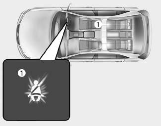
■ Instrument cluster
As a reminder to the driver, the seat belt warning light will illuminate for approximately 6 seconds each time you turn the ignition switch ON regardless of belt fastening.

Copyright © 2025 www.hi30.net