Hyundai i-30: Dual Clutch Transmission Control System / DCT Control Module (TCM)
Hyundai i30 (PD) 2018-2025 Service Manual / DCT(Dual Clutch Transmission) System / Dual Clutch Transmission Control System / DCT Control Module (TCM)
Description and operation
| Description |
| • |
Function
The Transmission Control Module (TCM) is like the brain for the Dual
Clutch Transmission (DCT). It receives information from various sensors
for a wide range of transmission controls to provide an optimal driving
environment for the driver. The TCM is programmed for optimal operation
in all driving conditions. If the TCM malfunctions, store the failure
information in memory and provide the error information to a mechanic
for fast and accurate repair.
|
Components and components location
| Components |

|
1. Fork cover 2. Clutch actuator & TCM assembly 3. Clutch actuator assembly |
4. O-ring 5. DCT control module (TCM) |
Schematic diagrams
| Connector and Terminal Function |

|
Pin |
Description |
Pin |
Description |
|
1 |
Ground 2 (Power) |
14 |
Battery power 2 (Motor) |
|
2 |
Ground 1 (Power) |
15 |
Battery power 1 (Motor) |
|
3 |
Shift lock solenoid |
16 |
Battery voltage (Low Power) |
|
4 |
Paddle shift "Up" |
17 |
P-CAN 1 Low |
|
5 |
Paddle shift "Down" |
18 |
P-CAN 1 High |
|
6 |
Inhibitor switch signal "R" |
19 |
Local-DCT 1 Low |
|
7 |
Inhibitor switch signal "N" |
20 |
Local-DCT 1 High |
|
8 |
Inhibitor switch signal "D" |
21 |
Local-DCT 2 Low |
|
9 |
Inhibitor switch signal "P" |
22 |
Local-DCT 2 High |
|
10 |
- |
23 |
PT-Local 1 Low |
|
11 |
Ignition voltage |
24 |
PT-Local 1 High |
|
12 |
Input speed sensor signal 2 (Even) |
25 |
Input speed sensor signal 1 (Odd) |
|
13 |
Input speed sensor power 2 (9 V) |
26 |
Input speed sensor power 1 (9 V) |
Repair procedures
| Inspection |
| Transmission Control Module (TCM) Inspection Procedure |
| 1. |
Inspecting TCM ground circuit: Measure the resistance between the TCM
and chassis ground.
(Check the terminal connected to the chassis ground while using the
back of the harness connector as the base point for TCM.)
|
| 2. |
Inspecting the TCM connector: Disconnect the TCM connector and visually
inspect to see whether there is a bend on the ground terminal of the
harness connector. Also visually check the connection pressure.
|
| 3. |
If no problem is found during inspection in step 1 and step 2, then
the problem is with the TCM itself. In this case, replace the TCM and
inspect the vehicle again.
|
| 4. |
Re-inspecting TCM: Install the TCM that was determined to have malfunctioned
from step 3 in another vehicle. Reset the error code and then check
the operation in that vehicle. If the vehicle operates without any problems,
then inspect the first vehicle with the initial problem again.
|
| Removal |
| 1. |
Prior to replacing the TCM, check the TCM clutch compensation value
with the diagnostic tool tool.
|
| 2. |
Turn ignition switch OFF and disconnect the battery negative (-) terminal.
|
| 3. |
Remove the clutch actuator assembly.
(Refer to Dual Clutch Transmission Control System - "Clutch Actuator
Assembly")
|
| 4. |
Loosen the bolts (A) and then removing the TCM (B).
|
| Installation |
| 1. |
To install, reverse the removal procedure.
|
| 2. |
Perform the clutch compensation value setting procedure using the diagnostic
tool after replacing TCM.
|
| 3. |
Perform the clutch touch point learning procedure using the diagnostic
tool after replacing TCM
|
 Description and operation
Description
The Dual Clutch Transmission (DCT) control system measures required data to
identify the state of the control target and computes the appropriate compensation
value if adjustment is necessary...
 Clutch Actuator & TCM Assembly
Specifications
Specification
Item
Specification
Rated voltage
12V
Rod length
79...
Other information:
Hyundai i30 (PD) 2018-2025 Owner's Manual: Fuses
A vehicle’s electrical system is protected from electrical overload damage by fuses. This vehicle has 2 (or 3) fuse panels, one located in the driver’s side panel bolster, the other in the engine compartment. If any of your vehicle’s lights, accessories, or controls do not work, check the appropriate circuit fuse...
Hyundai i30 (PD) 2018-2025 Owner's Manual: Child-protector rear door locks
The child safety lock is provided to help prevent children seated in the rear from accidentally opening the rear doors. The rear door safety locks should be used whenever children are in the vehicle. The child safety lock is located on the edge of each rear door...
Categories
- Manuals Home
- 3rd Generation i30 Owners Manual
- 3rd Generation i30 Service Manual
- Brake/clutch fluid
- Exhaust System (DPF) Warning Light. Glow Indicator Light
- Light bulbs
- New on site
- Most important about car
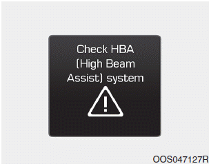
Warning light and message

When the High Beam Assist (HBA)
System is not working properly, the
warning message will come on for a
few second. After the message disappears,
the master warning light ( )
will illuminate.
Copyright © 2025 www.hi30.net


