Hyundai i-30: Charging System / DC DC converter
Hyundai i30 (PD) 2018-2025 Service Manual / Engine Electrical System / Charging System / DC DC converter
Description and operation
| Description |
Due to the considerably more frequent occurrence of starting operations, the
electrical load that occurs often leads to voltage dips in the vehicle network.
In order to stabilize the power supply for certain voltage-sensitive electrical
components, a DC/DC converter is used in conjunction with the ISG function.
The DC DC converter supplies the relay with a voltage that also remains constant
during the starting operation.
Via the test leads for input voltage and the start relay , the electronics decide
whether the power is supplied to the output via the bypass or the DC/DC converter.
In the bypass mode, the on-board supply voltage is not fed across the DC/DC
converter, rather is transferred directly to the outputs. In the booster phase,
the vehicle voltage is adapted.
| Operation Principle |

|

Components and components location
| Component Location |

| 1. DC/DC converter
[200W] |
2. DC/DC converter
[400W] |
Schematic diagrams
| Circuit Diagram |
| [200W] |

| [400W] |

Repair procedures
| Removal |
[200W]
| 1. |
Turn the ignition switch OFF and disconnect the battery negative (-)
terminal.
|
| 2. |
Disconnect the DC/DC converter connector (A).
|
| 3. |
Remove the DC/DC converter (B) after removing the nuts.
|

[400W]
| 1. |
Turn the ignition switch OFF and disconnect the battery negative (-)
terminal.
|
| 2. |
Remove the crash pad center lower cover.
(Refer to Body (Interior and Exterior) - "Main Crash Pad Assembly")
|
| 3. |
Disconnect the DC/DC converter connector (A).
|
| 4. |
Remove the DC/DC converter (B) after removing the nuts.
|

| Installation |
| 1. |
Install in the reverse order of removal.
|

 Alternator
Description and operation
Description
The Alternator has eight built-in diodes, each rectifying AC current to DC current.
Therefore, DC current appears at alternator "B" terminal...
 Battery
Description and operation
Description
AGM Battery
AGM battery is used for especially heavy load on the vehicle network depending
on equipment and requirements...
Other information:
Hyundai i30 (PD) 2018-2025 Owner's Manual: Smart cruise control (SCC) with stop & go system
➀ Cruise indicator ➁ Set speed ➂ Vehicle-to-vehicle distance To see the SCC screen on the LCD display in the cluster, select ASSIST mode (). For more information, refer to “LCD Display Modes” in chapter 3. The Smart Cruise Control System allows you to program the vehicle to maintain constant speed and minimum distance between the vehicle ahead...
Hyundai i30 (PD) 2018-2025 Service Manual: Power Window Motor
Components and components location Components Schematic diagrams Circuit Diagram Repair procedures Inspection • When removing with a flat-tip screwdriver or remover, wrap protective tape around the tools to prevent damage to components...
Categories
- Manuals Home
- 3rd Generation i30 Owners Manual
- 3rd Generation i30 Service Manual
- Battery replacement
- Shift-lock system. Shift-lock release
- Exhaust System (DPF) Warning Light. Glow Indicator Light
- New on site
- Most important about car
Turn signals and lane change signals
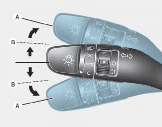
To signal a turn, push down on the lever for a left turn or up for a right turn in position (A). To signal a lane change, move the turn signal lever slightly and hold it in position (B).The lever will return to the OFF position when released or when the turn is completed.

Copyright © 2025 www.hi30.net